Background
In the event that you are having issues with your microARC 4, and discover that pins are burned on your power connector, follow the document below for instructions on how to fix your unit and get back to making chips!
microARC Motor Replacement
Tools
-
T10 Torx Screwdriver
-
Metric Allen Key Set
-
#1 Phillips Screwdriver
-
Crescent Wrench
-
Magnetic Dish
-
Cutting Pliers
Parts Needed
-
microARC Motor (PN 38432)
Motor Replacement
-
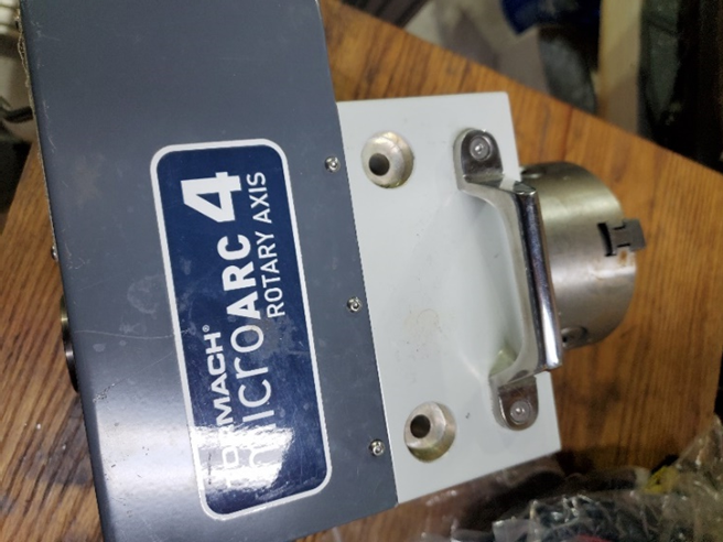
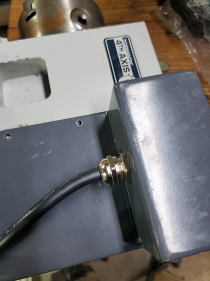
Power off the machine and disconnect the MicroArc cable from the machine bulkhead connector. Remove the retaining ring from the back of the motor, the button head screws from motor cover, and loosen the cable gland from the cover. Set all screws in a magnetic dish.
-
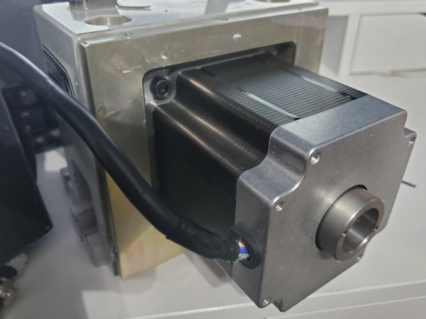
Feed the motor cable through the cable gland until you have approx. 2 feet (50cm) of cable left. Set the cover to the side. Remove the 4 screws securing the motor to the housing. Remove the 6 Torx screws holding the drive adapter to the motor flange.
-
Cut the motor cable, remove the cable end and motor. Remove the cable gland and gland nut from the original cable. Discard both the cut cable end and original motor. Feed the replacement cable through the cover as show, from the inside out. Feed the cable gland, gland nut, and replacement connector shell onto the replacement motor cable as shown.
-
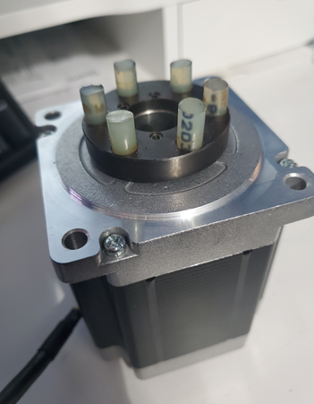
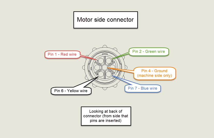
Connect the motor pins to the replacement connector according to the below image. The pin number is stamped next to its cavity. The image is shown looking at the back of the connector (pins will be inserted in the side that threads into the connector shell pictured above).

-
Ensure the wires are seated fully with a light tug. The wires should snap into position. If a wire is placed in an incorrect cavity, use the pin removal tool to remove the wire and reseat it in the correct cavity.
-
Thread the shell onto the connector and secure the shell with the two Phillips screws. Secure the drive adapter to the replacement motor, attach the motor to the housing, and feed the motor cable through the cover until there is only 3-4 inches (75-100mm) of slack in the cover. Secure the cable gland nut and reattach the cover.
-
Reconnect the motor cable to the machine bulkhead, power on the machine, and test the MicroArc functionality.
WARNING! DO NOT CONNECT THE 4th AXIS WITH THE MACHINE BULKHEAD POWERED OR DAMAGE TO THE MACHINE OR 4th AXIS CAN OCCUR.
Connector Pin Replacement
Tools
-
#1 Phillips Screwdriver
-
Magnetic Dish
-
Needle Nose Pliers
-
Metric Allen Key Set
Parts Needed
-
Machine Side Connector (30235) and 5x Female Pins (30774)
-
Alternatively, machine side wire harness (31189). Includes assembled 30235, 30774, 36in wires. Included 6ft wire not used.
-
-
Motor Side Connector (30480) and 5x Male Pins (30777)
Pin Replacement
-
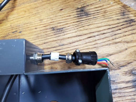
Power off the machine. Disconnect the 4th axis cable from the machine side connector. If you are replacing the motor side connector, remove the 2 Phillips screws holding the clamp and unscrew the rear portion of the connector. If you are replacing the machine side connector, unscrew the connector from the electrical cabinet. Push or pull out the original pins from the connector.
-
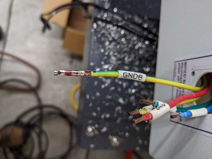
Use needle nose pliers or a punch less than .100” (2.54mm) diameter to push/pull the original pin from the wire. Replace the pin and crimp around the wire with needle nose pliers to secure pin. When crimping ensure that the pin’s inner tabs are secured around bare wire and the bottom tabs are secured around insulation as shown below.
-
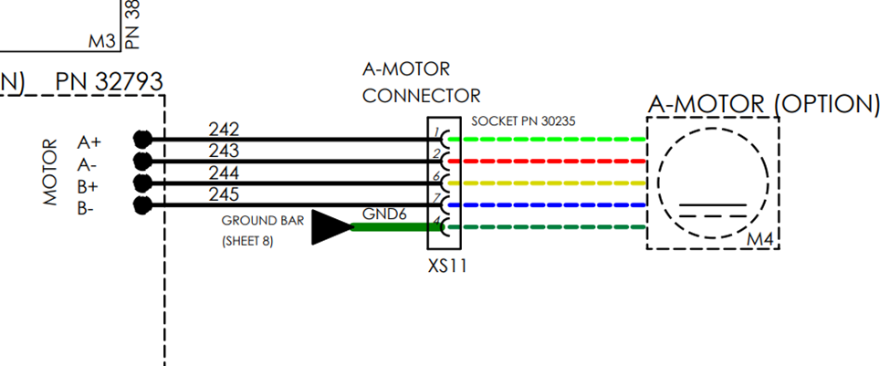
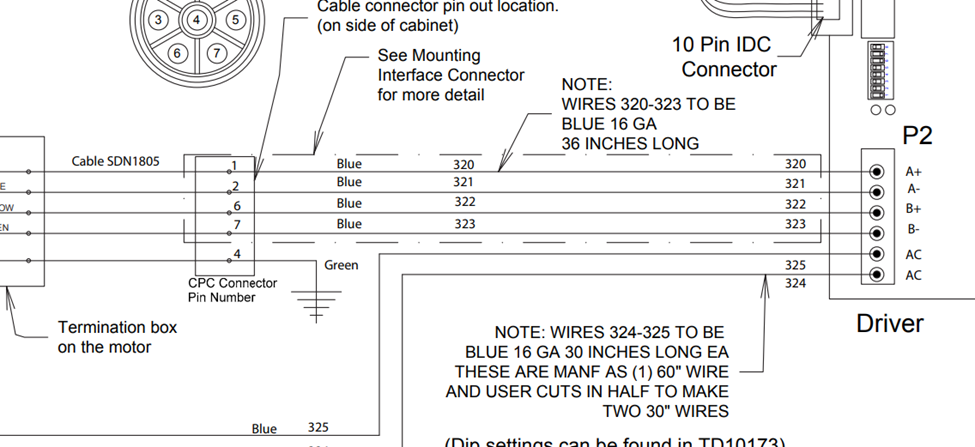
After securing all pins, insert the pins into the connector according to the chart below. The pin position differs between which connector you are working on, ensure that you are looking at the correct image. If your machine side wires are not colored according to the below image, skip to the next step.

-
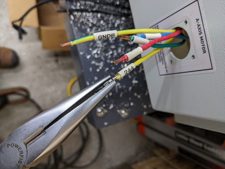
The machine side wire numbers will differ depending on the machine model. The two pictures below show the PCNC and M/MX wire numbers as examples. Trace the wires as needed to make connections to the machine side connector. The A+ wire on the stepper driver will connect to pin 1 of the machine side connector, A- to pin 2, Ground to pin 4, B+ to pin 6 and B- to pin 7.
-
With a light tug, ensure that each pin is fully seated in the connector. Reassemble the connector (motor side) or remount it (machine side). Reconnect the 4th axis cable and power on the machine. Test the 4th axis rotation at jogging and rapid speeds.