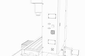
After installing the base machine, you must verify the installation. Complete the following steps in the order listed.
Power On the Machine
-
Use a multimeter to verify that the electrical service in your location meets the following requirements. If your location does not meet these requirements, do not install the machine. Instead, you must consult with a local electrician about your options.
-
Primary Power Required Single-Phase 230 Vac, 50/60 Hz
Maximum 240 Vac, 50/60 Hz -
Recommended Circuit Amperage Dedicated 20 A breaker
Maximum 60 A breaker
-
-
Connect the machine's mains power cable to the verified electrical service.
-
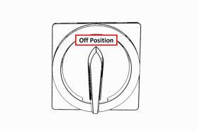
Find the Main Disconnect switch, and then remove the hang tag (if present).
-
Turn the Main Disconnect switch to ON.
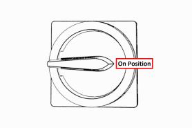
Mains power is now connected to the machine.
-
Push the Power button on the PathPilot controller, if it's not already powered on.
-
Push the Power button on the monitor, if it's not already powered on.
-
Follow the on-screen instructions to configure the PathPilot operating system and PathPilot controller.
When configuration is complete, the PathPilot operating system launches.
NOTE: After you first configure PathPilot, the operating system automatically launches whenever it's powered on. -
Depending on which monitor you have, do one of the following:
-
Standard Monitor Go to the next step.
-
Touch Screen Monitor You must first make sure that the monitor is configured and calibrated. From the PathPilot interface, in the MDI Line DRO field, type Admin Touchscreen. Then, select the Enter key, and follow the on-screen instructions.
-
-
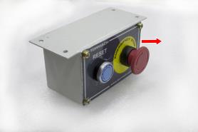
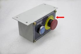
Rotate the Emergency Stop button on the operator box one-quarter turn clockwise to release it.
-
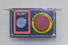
Push the blue Reset button to enable the machine.
The axis drives are now powered on.
-
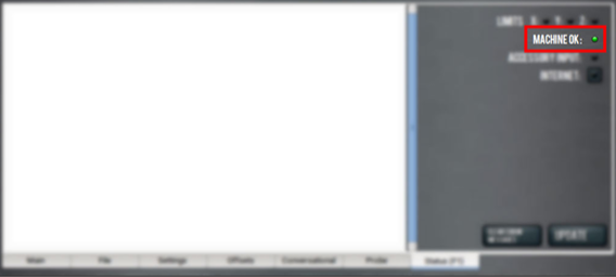
Verify that the blue Reset LED on the operator box comes on. From the PathPilot interface, on the Status tab, verify that the Machine OK light changes from yellow to green.
Once both are on, the machine is powered on and ready to operate.
-
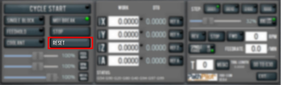
Select Reset.
Verify Axes Function
You must confirm that the axes correctly operate.
-
Power on the machine and bring it out of Reset.
-
Select the Page Up key on the keyboard to move the spindle head up (Z+).
-
Remove and discard the shipping block from the machine table.
-
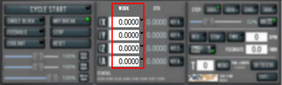
Reference the axes: from the PathPilot interface, select Ref Z, Ref X and Ref Y.
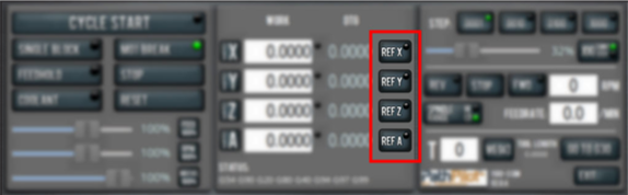
The machine moves to the reference position.
-
Use the keyboard to verify axes motion:
-
Select the Right Arrow key and then the Left Arrow key.
The table moves left (X+), then right (X-). -
Select the Down Arrow key and then the Up Arrow key.
The table moves away from you (Y-), then toward you (Y+). -
Select the Page Down key and then the Page Up key.
The spindle head moves down (Z-), then up (Z+).
-
-
If applicable, verify the optional Jog Shuttle:
-
Press any axis button on the Jog Shuttle — X, Y, Z, or A — to select an axis.
-
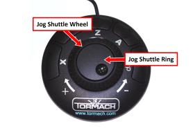
From the PathPilot interface, on the Main tab, the corresponding green Axis light comes on.
b. Turn the Jog Shuttle Ring in any direction to move the selected axis, then turn it in the opposite direction to reverse the direction.
Verify Spindle Function
You must confirm that the spindle correctly operates.
-
Open the spindle door and locate the spindle belt.
-
From the PathPilot interface, confirm that the Spindle Range button matches the spindle belt position.
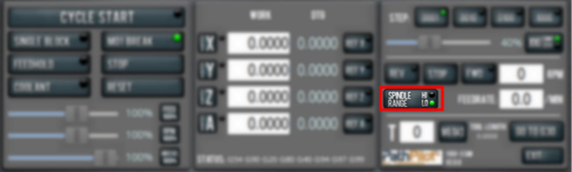
If necessary, select Spindle Range to match the spindle's belt position.
-
Close and latch the spindle door.
-
From the PathPilot interface, confirm that the Spindle Override slider isn't set to 0% (when it's set to 0%, the slider is yellow). To clear the override, select RPM 100%.
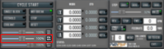
NOTE: The Spindle Override slider changes the programmed spindle speed by a specific percentage. If it's set to 0%, the spindle won't move during the following steps in this procedure. For information, see “About Spindle Override”.
NOTE: If you have an Operator Console, make sure the RPM knob isn’t set to 0%. If it is, turn the RPM knob.
-
From the PathPilot interface, in the RPM DRO field, type 500. Then select the Enter key.
-
Select FWD.
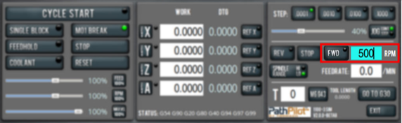
The spindle rotates clockwise (viewed from above) at 500 rpm.
-
Select STOP.
The spindle stops rotating. -
Select REV.
The spindle rotates counterclockwise (viewed from above) at 500 rpm. -
Select STOP.
The spindle stops rotating. -
In the RPM DRO field, type 1000. Then select the Enter key.
-
Select FWD.
The spindle rotates clockwise (viewed from above) at 1000 rpm. -
Repeat the procedure at 1000 rpm.
Power Off the Machine
-
Push the Emergency Stop button to lock it into the disabled position.
With the Emergency Stop button in the disabled position all motion and spindle function stops, the Reset button is disabled , and the blue Reset LED goes off. From the PathPilot interface, on the Status tab, the Machine OK light illuminates yellow.
-
From the PathPilot interface, select Exit.
-
When prompted, select OK.
-
Once the PathPilot interface indicates that it's safe to power off the machine, turn the Main Disconnect switch to OFF.
Mains power is disconnected from the machine.
Looking for more information?
This is a section of the 1100MX operator's manual. To view the whole manual, go to Tormach document UM10586.
If you have additional questions, we can help. Create a support ticket with Tormach Technical Support at tormach.com/how-to-submit-a-support-ticket for guidance on how to proceed.