Required Tools
This procedure requires the following tools. Collect them before you begin.
-
Adjustable wrench
-
Dead-blow hammer
-
Magnetic dial test indicator
-
Metric hex wrench set
-
Rust preventative
Install the Tool into the Quick Change Tool Holder
-
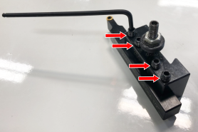
Find a tool and its equivalent tool holder, and put the tool into the tool holder. Lock the tool into the tool holder: with the tool pointing toward you, tighten the hex head screws.
-
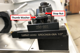
Set the rough tool height by adjusting the thumb screw. Then, secure it in place with the stop nut. You'll make fine adjustments later in this procedure to bring the tool plane on center with the spindle.
-
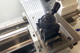
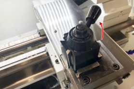
To attach the tool holder, the tool post must be in the unlocked position: move the tool post handle up.
-
Put the tool holder onto the tool post, and then move the tool post handle down to the locked position.
-
Before operating the machine, you must make sure that the quick change tool holder is aligned. Go to "Align the Tool".
To Use a Boring Bar
-
To attach the tool holder, the tool post must be in the unlocked position: move the tool post handle up.
-
Put the tool into the boring bar holder.
-
Put the tool holder onto the tool post, and then move the tool post handle down to the locked position.
-
Lock the tool into the tool holder: tighten its two hex head screws.
Tip! When you remove the tool, loosen the hex head screws, and gently tap them with a dead-blow hammer.
Align the Tool
-
Power on the machine and the PathPilot controller.
-
Turn the Main Disconnect switch to ON, on the side of the electrical cabinet.
-
Twist out the machine's red Emergency Stop button, which enables movement to the machine axes and the spindle.
-
Press the Reset button.
-
Bring the machine out of reset and reference it.
-
-
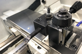
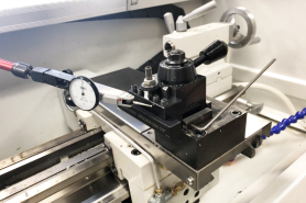
Attach a magnetic dial test indicator to the spindle.
-
Put the indicator tip on the face of the tool holder.
-
Slowly jog the machine along the X-axis to move the indicator tip along the face of the tool.
-
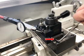
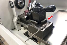
Adjust the quick change tool post alignment as necessary: use a 3 mm hex wrench to adjust the two set screws on the front and right sides of the quick change tool post risers to clock the tool post until the indicator reads zero.
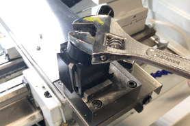
-
Securely tighten the tool post nut with an adjustable wrench.
-
Repeat Steps 4 through 5 to make sure that the tool post is still correctly aligned after tightening the tool post nut.
Looking for more information?
This is a section of the 8L operator's manual. To view the whole manual, go to Tormach document UM10753.
If you have additional questions, we can help. Create a support ticket with Tormach Technical Support at tormach.com/how-to-submit-a-support-ticket for guidance on how to proceed.