Before You Begin
Prerequisites
-
The machine is in its final location and rough leveled.
-
The following components must be installed:
-
Enclosure
-
Operator console
-
Flood coolant tank
NOTE: If you haven't yet done so, don't connect any of the coolant pumps to the machine. -
The site must have 240 Vac, single phase-power available (20 A).
-
Required Tools
-
Engine hoist
-
Flat-blade screwdriver
-
Hammer
-
Lifting strap rated for at least 1,000 lb (454 kg), 2
-
Metric hex wrench set
-
Pry bar
-
Wire snips
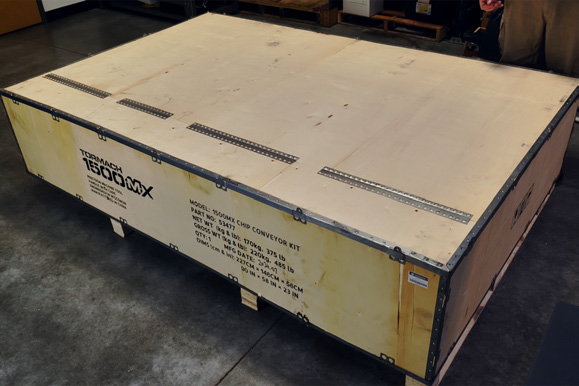
Unpack and Assemble the Chip Conveyor Kit
-
Cut the straps on the shipping crate with wire snips, and remove the top and sides of the crate with a hammer and pry bar.
-
Remove and discard the packaging protecting the chip conveyor on the pallet.
-
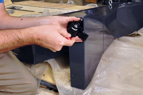
Identify the two casters and eight M6 × 1 - 12 button head cap screws included with this kit.
-
With the chip conveyor still on the pallet and laying on its side, install the two casters onto the end of the chip conveyor with a 5 mm hex wrench.
-
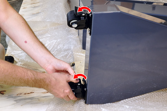
Lock the casters to prevent the wheels from spinning while lifting the chip conveyor from the pallet.
-
Remove and set aside the remaining boxes and additional packaging from the pallet.
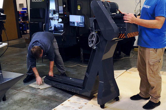
WARNING! Tip Hazard: Use at least two people to lift the machine into an upright position. You must use proper lifting techniques and keep the machine stable throughout the process. Failure to do so could result in serious injury or equipment damage.
-
Slide the chip conveyor to the edge of the pallet. With the help of an assistant, slowly lift the chip conveyor upright, and lower it onto the ground.
-
Discard the pallet and any remaining packaging.
Prepare the Coolant Tank
-
Power off the machine and the PathPilot controller.
-
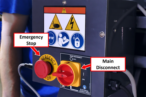
Push in the machine's red Emergency Stop button, which removes power to motion control.
-
From the PathPilot interface, select Exit.
-
Turn the Main Disconnect switch to OFF on the side of the electrical cabinet.
-
-
If you've already installed the flood coolant kit, the washdown coolant kit, or the through-spindle coolant kit, disconnect the hoses from the coolant pumps, and disconnect the pumps' power cords from the machine.
-
Remove the following items from the coolant tank, which aren't used with the chip conveyor:
-
Chip baskets.
-
Two cover panels on either side of the chip baskets, using a 3 mm hex wrench.
We recommend storing these items for future use.
-
-
Roll the coolant tank to the work area where you've unpacked the chip conveyor.
Lift and Install the Chip Conveyor
We recommend using an engine hoist and lifting straps rated for at least 1,000 lb (454 kg) to safely lift and position the chip conveyor into the coolant tank. You must have an assistant to guide the conveyor into position during this process. Follow the steps below carefully to avoid personal injury or damage to the equipment.
-
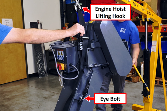
Position the engine hoist behind the front leg of the chip conveyor.
-
Secure a lifting strap to each eye bolt on either side of the front leg of the chip conveyor. Attach the front lifting straps to the lifting hook on the engine hoist.
-
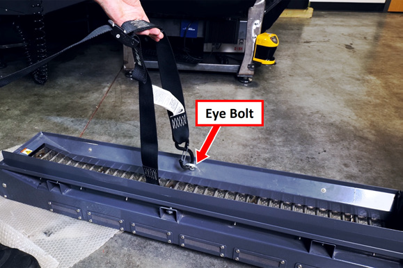
Attach another set of lifting straps to the eye bolts on the rear section of the chip conveyor. These straps will be used to guide the conveyor into the coolant tank.
WARNING! Transportation and Lift Hazard: Before moving the machine, you must confirm that all persons are clear of the area below the machine. Qualified professionals must transport, lift, and move the machine. Moving parts can entangle, pinch, or cut you, causing death or serious injury.
-
Verify that all lifting straps are secure and that the load is balanced. Slowly raise the engine hoist to lift the front leg of the chip conveyor off the ground.
-
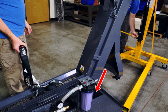
While the front leg is lifted, have an assistant guide the rear of the conveyor using the lifting strap. Carefully lower the conveyor into the coolant tank, ensuring it aligns with the tank.
-
Gradually lower the engine hoist to set the rear of the conveyor inside the coolant tank.
-
Verify that the chip conveyor is fully seated and aligned within the tank, and that the front leg is stable on the floor. Remove the lifting straps.
-
Identify the three cover panels and the 24 M5 × 0.8 - 10 button head cap screws included with this kit.
-
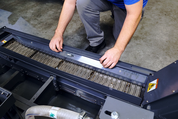
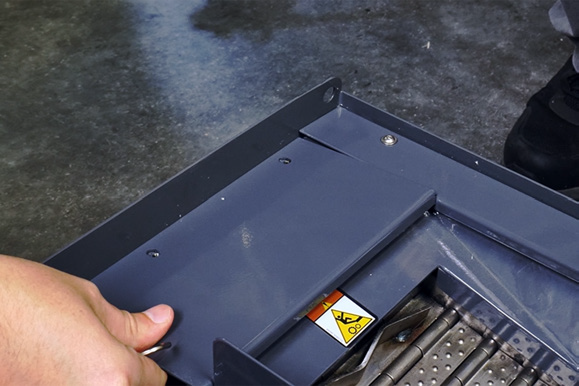
Loosely install the three cover panels onto the coolant tank with a 3 mm hex wrench:
-
Install the narrow panel along the side of the tank, making sure that the flange on the panel hooks into the inside of the chip conveyor.
-
b. Install the short panel at the end of the tank.
c. Install the wide panel between the conveyor and the pumps.
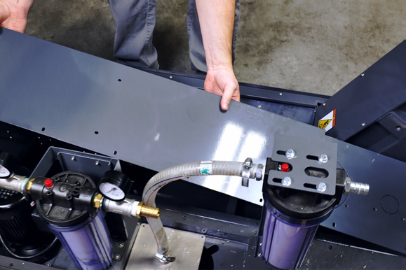
NOTE: The knock-outs on the wide panel are used to mount the oil skimmer. If you have an oil skimmer, remove the knock-outs before installing the panel.
d. Tighten the screws on all three panels.
-
Unlock the casters on the conveyor, and roll the chip conveyor and coolant tank assembly to the back of the machine.
Make Connections
-
Connect the power cables and the coolant hoses for the flood coolant pump and, if installed, the washdown coolant pump and the through-spindle coolant pump.
-
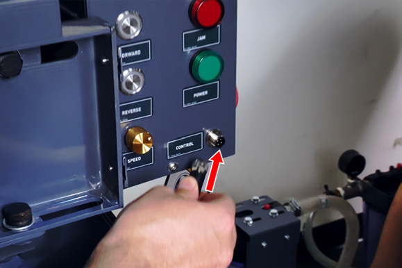
Identify the control cable for the chip conveyor. Connect one end to the Control port on the chip conveyor's control box.
-
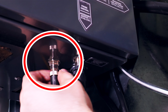
Route the loose end of the control cable to the bottom of the machine's electrical cabinet, and connect it to the Accessory Output 1 port.
-
Connect the chip conveyor’s power cable to a 220 Vac wall outlet.
-
Secure the cables and hoses at the back of the machine with cable ties, making sure to position them so that they won't interfere with any moving parts.
Verify the Installation
-
With the machine still powered off, identify the Main Disconnect switch on the chip conveyor’s control box. Turn it to the on position.
-
Twist out the Emergency Stop button on the chip conveyor.
-
Turn the Speed knob to the halfway position.
-
Test the forward and reverse controls:
-
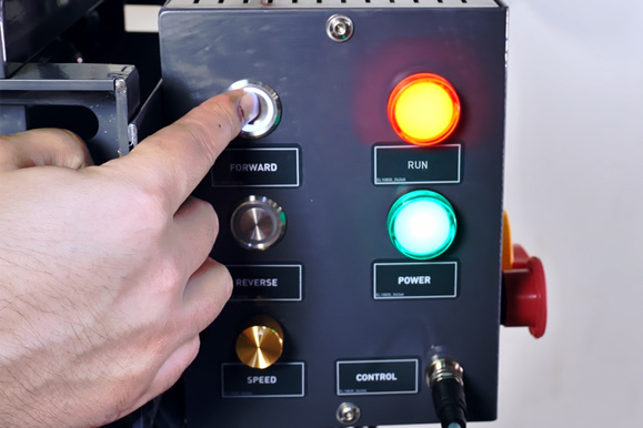
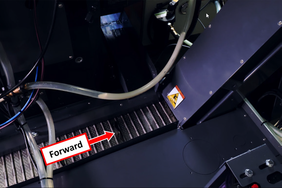
Press and hold the Forward button on the chip conveyor control box. The chip conveyor runs forward (toward the control box), and the Run light illuminates.
-
b. While holding the Forward button, push in the Emergency Stop button on the chip conveyor.
The chip conveyor stops running.
c. Release the Forward button, and twist out the Emergency Stop button.
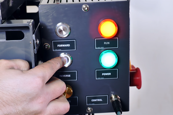
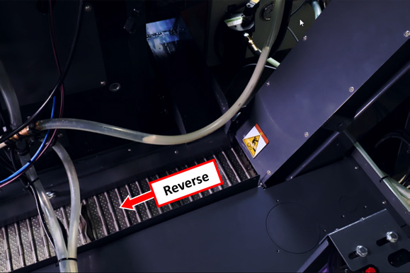
d. Press and hold the Reverse button on the chip conveyor control box. The chip conveyor runs backwards (away from the control box), and the Run light illuminates.
e. While holding the Reverse button, push in the Emergency Stop button on the chip conveyor.
The chip conveyor stops running.
-
Power on the machine and the PathPilot controller.
-
Turn the Main Disconnect switch to ON on the side of the electrical cabinet.
-
Twist out the machine's red Emergency Stop button, which enables movement to the machine axes and the spindle.
-
Press the Reset button.
-
-
Observe the chip conveyor, which should not be running in either direction at this time.
-
Test the M-code controls:
-
From the PathPilot controller, in the MDI Line DRO field, type each of the following commands, one at a time, while observing the chip conveyor.
-
|
M-Code |
Expected Behavior |
|
M231 |
Turns on the chip conveyor. |
|
M233 |
Turns off the chip conveyor. |
|
M231 P10 Q20 |
Begins an on/off duty cylce: Turns on the chip conveyor, runs for 10 seconds, and then turns off for 20 seconds. The P~ word specifies the run duration in seconds. The Q~ word specifies the off duration in seconds. |
-
From the PathPilot controller, in the MDI Line DRO field, type M233. Then select the Enter key. The chip conveyor turns off.
-
Wait for two minutes, observing the chip conveyor to verify that it doesn't turn back on.
NOTE: For information on maintaining the chip conveyor, go to “Chip Conveyor Maintenance Schedule”.
Looking for more information?
This is a section of the 1500MX operator's manual. To view the whole manual, go to Tormach document UM10811.
If you have additional questions, we can help. Create a support ticket with Tormach Technical Support at tormach.com/how-to-submit-a-support-ticket for guidance on how to proceed.