Before You Begin
Prerequisites
-
The machine is in its final location and rough leveled.
-
The following components must be installed:
-
Flood coolant kit
-
Enclosure
-
Operator console
-
-
The ATC must not yet be installed.
Required Tools
-
#2 Phillips screwdriver
-
5/16 in. wrench
-
13 mm open-ended wrench
-
Adjustable wrench
-
Engine hoist with two 500 lb (180 kg) straps, or a chain with a center hook
-
Flat-blade screwdriver
-
Ladder
-
Metric hex wrench set
-
Wire snips
Unpack the Through-Spindle Coolant Kit
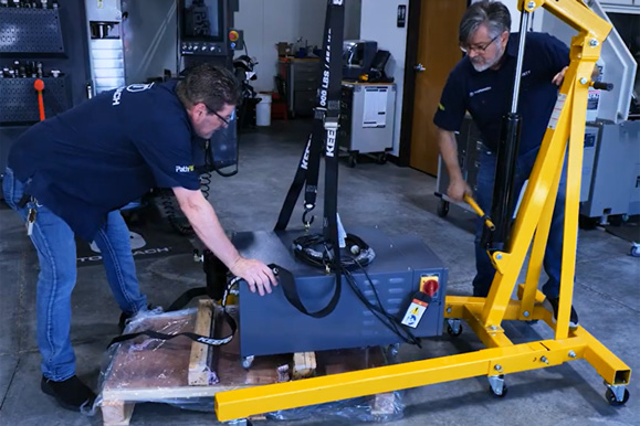
WARNING! Lifting Hazard: Only use suitable lifting equipment, ensuring that it's on a stable, level surface. Never lift over people. Heavy loads could tip, fall, or shift unexpectedly, causing death or serious injury.
-
The TSC pump is approximately 400 lb (180 kg). We strongly recommend lifting it from the shipping pallet with an engine hoist. Due to the uneven weight distribution (one side is heavier), have an assistant help to guide and stabilize the pump during the lift to prevent tipping or injury.
-
Remove the pallet, and slowly guide the pump to the ground.
-
Unpack the shipping box with the remaining components of the TSC kit.
Prepare the Machine for Installation
-
Power on the machine and the PathPilot controller.
-
Turn the Main Disconnect switch to ON on the side of the electrical cabinet.
-
Twist out the machine's red Emergency Stop button, which enables movement to the machine axes and the spindle.
-
Press the Reset button.
-
Bring the machine out of reset and reference it.
-
-
Position the table in the middle of the X- and Y- axis travels.
-
Jog the spindle all the way down in the Z-axis.
-
Power off the machine and the PathPilot controller.
-
Push in the machine's red Emergency Stop button, which removes power to motion control.
-
From the PathPilot interface, select Exit.
-
Turn the Main Disconnect switch to OFF on the side of the electrical cabinet.
-
-
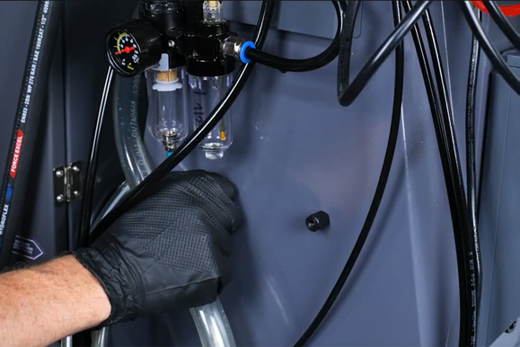
Disconnect the machine from the shop air supply.
Install the Coolant Pickup and Filter
-
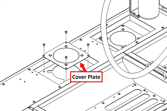
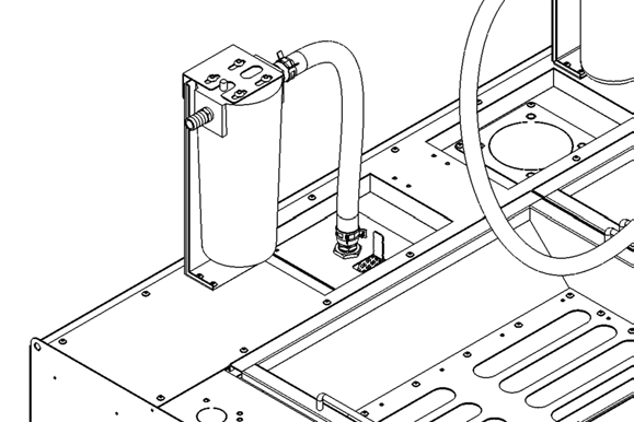
Standing behind the coolant tank, locate the coolant pump cover plate furthest to the right. Remove the four M5 screws securing the pump cover plate with a 3 mm hex wrench. Set the screws aside.
-
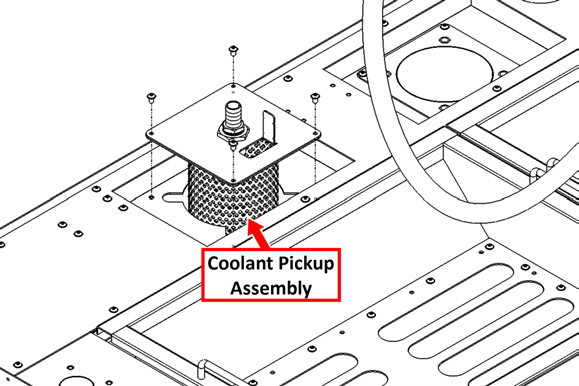
Identify the coolant pickup assembly included in this kit. Remove the four bolts and screws that secure the assembly together with a 5/16 in. wrench. Put the basket into the coolant tank hole, then put the coolant filter on top so that the opening flap is nearest to the machine. Secure the assembly to the coolant tank with the M5 screws that you set aside and a 3 mm hex wrench.
-
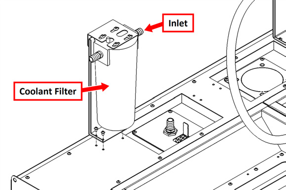
Identify the coolant filter assembly and four M5 screws included with this kit. Put it onto the coolant tank so that the inlet is facing the pickup assembly. Secure it to the coolant tank with four M5 screws and a 3 mm hex wrench.
WARNING! High-Pressure Hazard: Ensure all hose connections are secure and properly tightened. High-pressure coolant can cause hoses to burst or become dislodged if not correctly installed, leading to serious injury or equipment damage.
-
Identify the shortest PVC hose included in this kit. Using two 1.25 in. hose clamps, connect the hose between the barbed fitting on the pickup assembly and the inlet of the filter assembly.
-
Identify the longest piece of 3/4 in. ID PVC hose. Using two 1.25 in. hose clamps, connect the hose between the barbed fitting on the outlet of the filter assembly and the inlet of the TSC pump labeled Coolant Inlet.
-
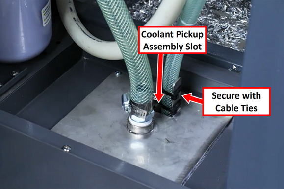
Identify the 1/2 in. ID PVC hose. Connect one end of the hose to the barbed fitting on the TSC pump labeled Pressure Relief with a 1 in. hose clamp. Insert the loose end into the slot on the top of the coolant pickup assembly, and secure it to the vertical tab with two cable ties.
Install the Rotary Union
-
Remove the M6 screws that secure the right side panel of the spindle head cover using an M4 hex wrench. Loosen the two screws on the bottom (in slots). Remove the right panel and set it aside, along with all of the screws.
-
From the left side panel, remove only the M6 screws securing the front edge to the front panel of the spindle head cover with an M4 hex wrench.
-
Remove the screws on the top of the front panel with an M4 hex wrench.
-
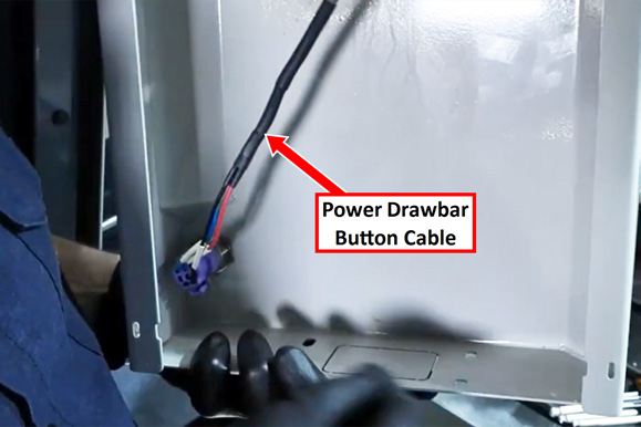
Before removing the remaining screws on the front panel, snip off the cable ties holding the power drawbar button cable along the inside edge of this panel.
-
Remove the screws along the bottom front edge of the panel and lower the panel slightly to access the cable along the top left. Snip the cable tie holding this cable in place.
-
Disconnect the power drawbar button cable from the front panel by pressing in the connector's latch and removing it from the drawbar button.
-
Remove the front panel and set it aside, along with all of the screws.
-
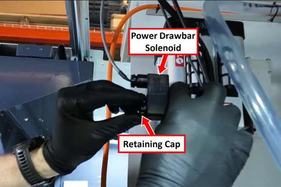
Remove the retaining cap from the drawbar solenoid. Let the solenoid dangle, but temporarily replace the cap to avoid losing it.
-
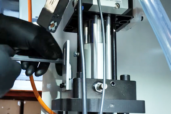
Remove the four socket head cap screws that secure the power drawbar to its mounting plate using a 10 mm hex wrench. Set the screws aside.
-
Press down on the push-to-connect fitting and disconnect the air line by pulling it out.
-
Lift the power drawbar away from the mounting plate, being careful not to tug on the cables. Then set the power drawbar aside.
-
Identify the piece of 1/4 in. OD tubing and the rotary union included in this kit. Insert one end of the tube into the push-to-connect fitting on the rotary union.
-
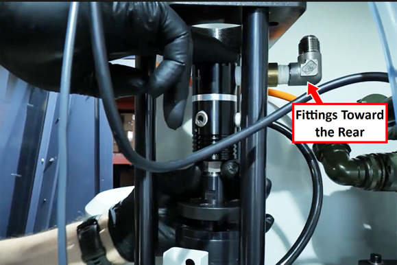
Orient the rotary union so that the fittings are pointed toward the rear of the machine.
-
Thread the rotary union into the top of the spindle and tighten with a 22 mm wrench.
IMPORTANT! The rotary union has a left-hand thread.
-
Re-install the power drawbar. Align the slot in the power drawbar extension with the fittings of the rotary union. Then secure it to the mounting plate with its original four screws that you set aside earlier.
-
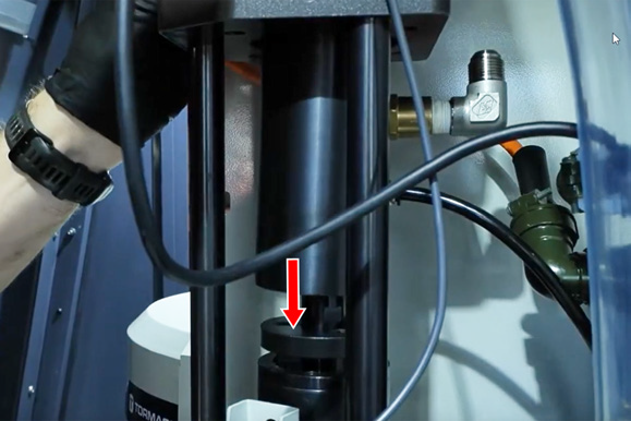
Reinstall the drawbar solenoid and secure it with its original retaining cap.
-
Reconnect the air line into the power drawbar's push-to-connect fitting.
Install the High-Pressure Hose
-
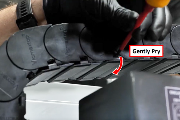
The high-pressure hose is routed through the energy chain. To avoid damaging other cables, we strongly recommend removing several of the retaining covers from the chain. Gently pry up each cover with a flat-blade screwdriver and lift them off, continuing down the chain, including around the electrical connection cover. Set the covers aside.
-
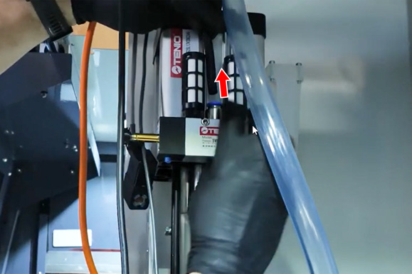
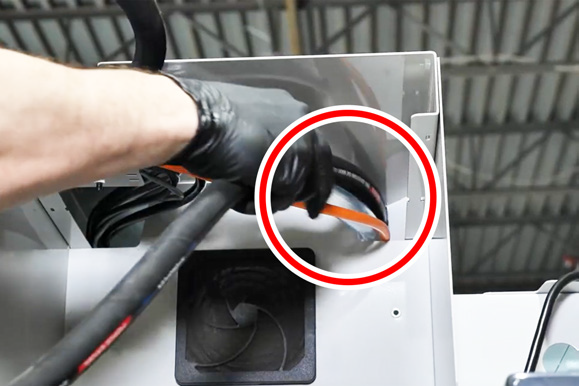
Identify the high-pressure hose included with this kit. Route it through the energy chain channel, curving it to run towards the pump. Pull the loose end of the hose through the top section of the energy chain and pass it through the opening on the top right of the spindle, guiding it toward the rotary union.
-
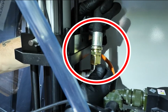
Attach the end of the hose to the rotary union and tighten the hose nut with an open-end wrench. You may need to use a second wrench to hold the rotary union’s extension in place while tightening.
-
At the top of the spindle head cover, cut off the front cable tie securing the cables. Re-secure the cable and the high-pressure hose to the channel with a new cable tie.
-
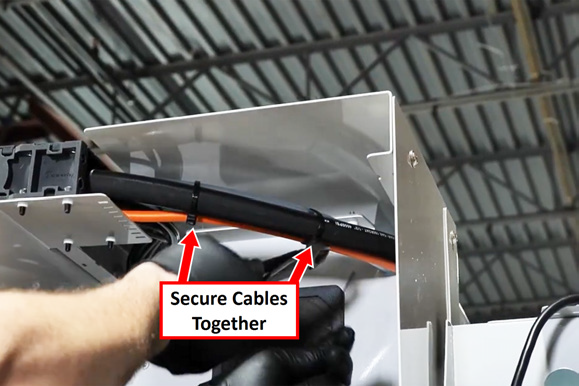
At the rear of the machine, adjust the hose so that it's the same length as the other cables running through the energy chain, then secure them all together with two cable ties.
-
Ensure that all cables are neatly arranged in the energy chain, and then replace the energy chain covers.
-
Reattach the drawbar button connector to the front cover. Align the front cover and resecure it with the screws that you set aside earlier. Then resecure the cables along both sides of the front cover using cable ties.
-
Route the loose end of the tubing down to the front of the spindle head cover.
-
Reinstall the right spindle cover with the screws that you set aside earlier.
Install the Hose Bracket
-
At the rear of the machine, locate the two threaded inserts.
-
Identify the two standoffs included with this kit, and install them into the two inserts with a 13 mm wrench.
-
Identify the hose bracket included with this kit, and align it onto the standoffs. Secure it with two cap head screws and a 5 mm hex wrench.
-
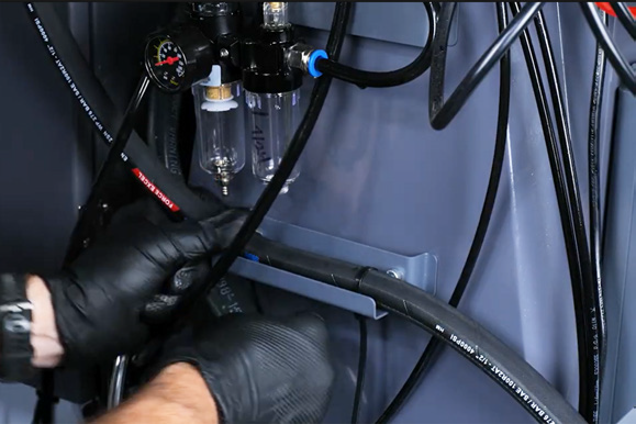
Put the high-pressure hose onto the bracket, and secure it with two cable ties.
Make Connections
-
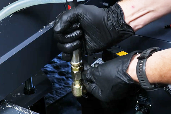
Remove the cap from the TSC pump's outlet, and attach the loose end of the high-pressure hose. Securely tighten it with an adjustable wrench.
-
Route the two electrical cables toward the electrical cabinet.
-
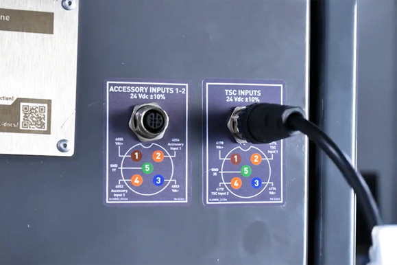
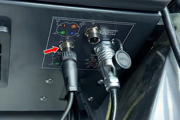
On the side of the electrical cabinet, connect the cable labeled TSC Sensor to the TSC Inputs outlet.
-
On the bottom of the electrical cabinet, connect the cable labeled TSC Control to the TSC Control outlet.
Securely Tighten Hose Clamps
WARNING! High-Pressure Hazard: Ensure all hose connections are secure and properly tightened. High-pressure coolant can cause hoses to burst or become dislodged if not correctly installed, leading to serious injury or equipment damage.
-
Double-check all hose clamps to verify that they're securely tightened.
Looking for more information?
This is a section of the 1500MX operator's manual. To view the whole manual, go to Tormach document UM10811.
If you have additional questions, we can help. Create a support ticket with Tormach Technical Support at tormach.com/how-to-submit-a-support-ticket for guidance on how to proceed.