The machine's pallet has spaces that allow you to slide the pallet out from underneath the machine without using a lifting device. You'll need to partially disassemble the pallet and raise up the machine by its feet to remove the pallet, as described in the following procedure.
CAUTION! Sharp Objects Hazard: Before opening the shipping crate, you must put on work gloves and safety eyewear that meets ANSI Z87+. If you don't, the shipping crate and steel straps could cut you, causing serious injury.
-
Put on work gloves and eye protection.
-
Remove and discard the plastic wrapped around the shipping crate.
-
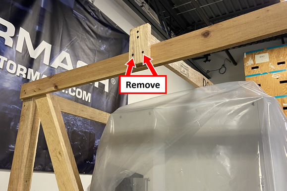
Disassemble the shipping crate, starting with the top and then the four sides. With an assistant, remove the bottom two screws on either side of the crate's top beam, and then remove it from the shipping crate.
-
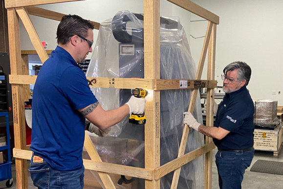
Remove the screws on each of the four sides of the shipping crate, starting at the bottom. With an assistant, lift the sides of the shipping crate off of the pallet.
-
Remove and discard the plastic wrapped around the machine and stapled to the crate.
-
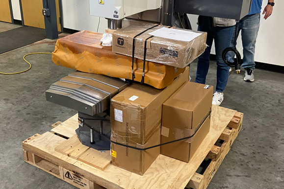
Remove and discard the shipping straps securing the accessory boxes (the machine owner's kit, a coolant filter, and, if not yet installed, the operator console kit).
-
Set aside the coolant filter box and the operator console box for later use, and open the machine owner's kit box.
-
Identify the three machine foot pads and the three machine foot spacers in the machine owner's kit.
-
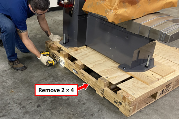
Remove the screws on the 2 × 4 on the left side of the pallet with an impact driver. Remove and discard the board.
-
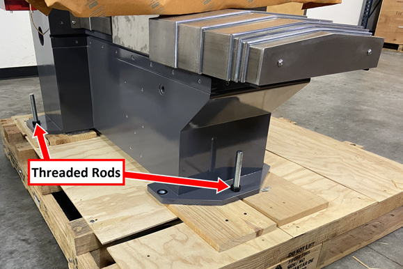
Identify the three threaded rods that attach the machine to the pallet. To prevent galling or seizing, we recommend using a high-quality anti-seize compound on the threads of the machine legs.
-
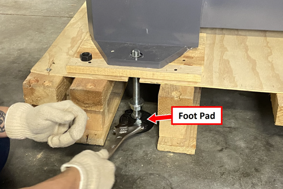
Starting with one of the threaded rods, loosen the nuts from the top and bottom with an adjustable wrench.
-
Put the machine's foot pad (from the machine owner's kit) under the threaded rod, and tighten the threaded rod into the foot pad.
-
Repeat Steps 10 and 11 for the two remaining threaded rods.
-
Raise the machine up by its three feet until there's a 1/8 in. gap between the pallet and the machine.
-
Remove the screws securing the plywood boards under each foot plate. Remove the boards off of the pallet and discard them.
-
Verify that the machine is stable and secure on its three feet.
-
Slide the pallet out from underneath the machine, taking care to do this slowly and evenly to avoid damaging the machine or pallet.
-
Remove the three machine foot spacers from the owner's kit, and remove and discard the plastic wrapped around them. You'll install the spacers on the threaded rods, under the foot plate.
WARNING! Crush Hazard: Make sure to lower the machine slowly and evenly to avoid sudden movements that could cause injury or damage the machine.
-
Begin lowering the machine toward the ground. Work your way around the machine, turning the hex nut on each threaded rod four or five times before moving to the next foot.
-
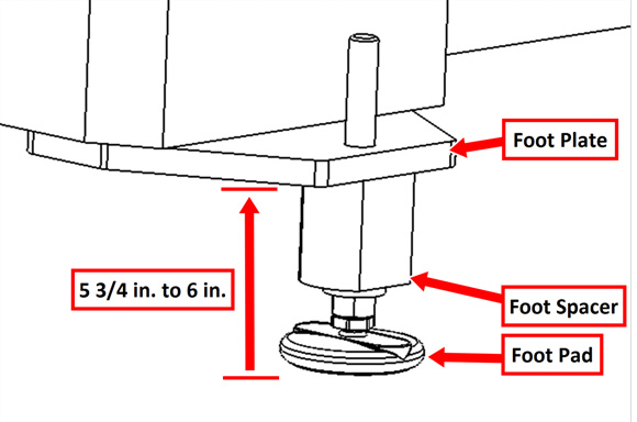
Continue lowering the machine until there's a 5 3/4 in. to 6 in. gap between the floor and the bottom of the machine's foot plates. Level all three foot plates to the same height.
-
Install a foot spacer below each of the machine's foot plates. Make sure that the large, flat side of the foot spacer is flush with the edge of the foot plate. Then, tighten the flat washer and nut against the bottom of the foot spacer.
-
Once the machine is safely on the ground, verify that it is stable and secure.
Looking for more information?
This is a section of the 1500MX operator's manual. To view the whole manual, go to Tormach document UM10811.
If you have additional questions, we can help. Create a support ticket with Tormach Technical Support at tormach.com/how-to-submit-a-support-ticket for guidance on how to proceed.
