Required Tools
-
3/16 in. hex wrench
-
4 mm hex wrench
-
Needle-nose pliers
-
Razor blade
-
Thread seal tape
Remove the Tubing from the Pump
We recommend mounting the MQL pump on the access panel on the back of the machine's column. If your unit was shipped with the tubing already connected to the pump, you’ll need to disconnect it to route it from the spindle to the pump, then reconnect it at the back of the machine.
NOTE: If your unit did not ship with the tubing already connected to the pump, you can skip this section. Go to "Route the Tubing".
-
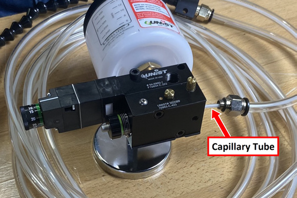
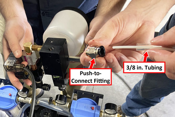
Unscrew the 3/8 in. push-to-connect fitting from the pump block.
-
Pull the outer 3/8 in. tube and push-to-connect fitting away from the pump block, exposing the 1/8 in. nylon capillary tube.
-
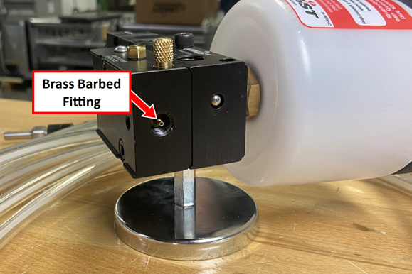
Grasp the 1/8 in. capillary tube with a pair of needle-nose pliers. Lever the pliers against the pump block to pull the capillary from the brass barbed fitting in the pump.
NOTICE! Don't use a razor blade to cut the capillary along its axis to remove it from the barb fitting. Doing so can damage the barbed fitting and result in system performance issues. Also, don't grab onto the barbed fitting itself with the pliers — make sure you're pulling on the tubing.
-
In the pump, verify that there's no remnants of the 1/8 in. capillary tube on the brass barbed fitting.
-
Remove the push-in fitting from the 3/8 in. tube, and set it aside.
-
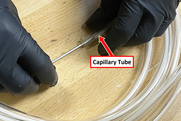
To reconnect the tubing to the pump (done later in this procedure), you'll need about 1 in. of the 1/8 in. capillary tube exposed from the 3/8 in. tube. If you need to expose the capillary tube, complete the following steps. Otherwise, go to the next section.
-
Carefully insert a hex wrench into the 3/8 in. tube, and lightly push back the 1/8 in. capillary tube.
-
b. While holding the capillary tube back with the wrench, cut the 3/8 in. tube with a razor blade.
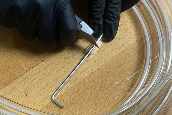
NOTICE! Don't cut the 3/8 in. tube where the blade could also cut the 1/8 in. capillary tube. If the capillary tube is accidentally cut, it could result in system performance issues.
Route the Tubing
-
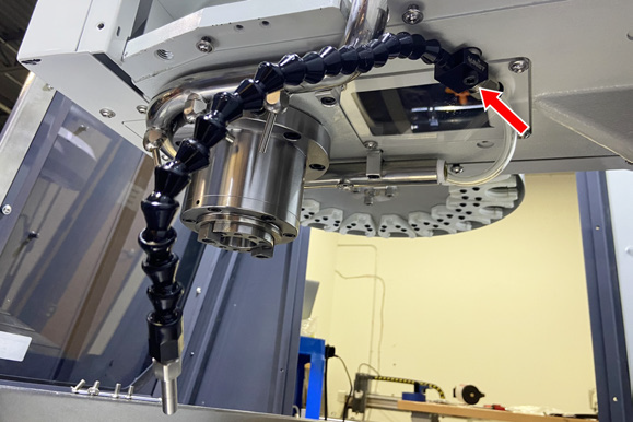
Mount the nozzle behind the spindle head with the included hardware and a 3/16 in. hex wrench.
-
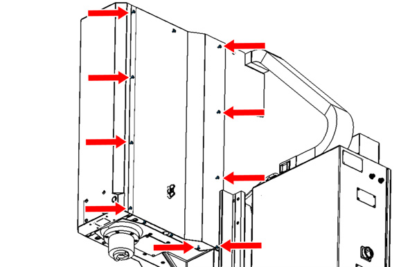
Remove the nine M6 flanged button head cap screws on the side of the right side spindle cover with a 4 mm hex wrench. Set the screws aside. Then, loosen or remove the three screws on the bottom of the spindle head cover. Remove the cover, and set it aside.
-
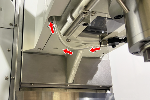
Route the tubing from the nozzle up through the hole on the bottom left of the spindle head casting. Continue up to the top of the spindle housing, and out through the top left hole.
-
From the back of the machine, route the tubing through the energy chain, taking care to keep all the contents in the energy chain free from twists.
Tip! It may help to raise the Z-axis to its maximum height, and remove a few of the energy chain cover panels to more easily route the tubing through the energy chain.
-
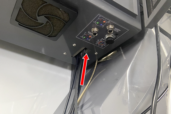
Route the tubing between the machine casting and the electrical cabinet.
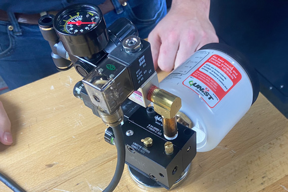
Mount the Pump
-
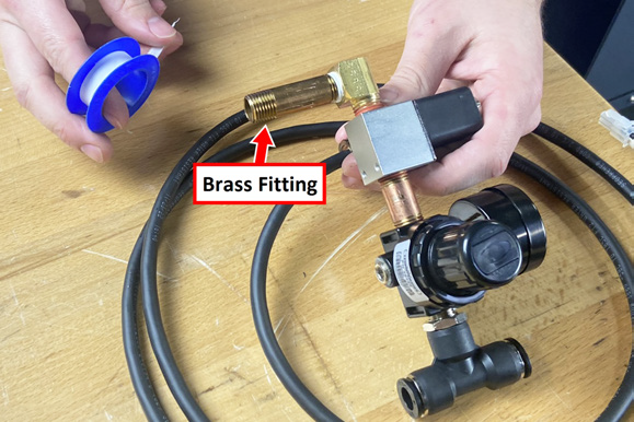
Identify the solenoid and pressure regulator assembly included with this kit. Wrap thread seal tape around the threads of the brass fitting on the solenoid.
-
Thread the brass fitting on the solenoid onto the pump.
-
Reinstall the push-to-connect fitting that you set aside earlier onto the 3/8 in. tube.
-
Carefully install the 1/8 in. capillary tube onto the barbed fitting on the pump with a pair of pliers.
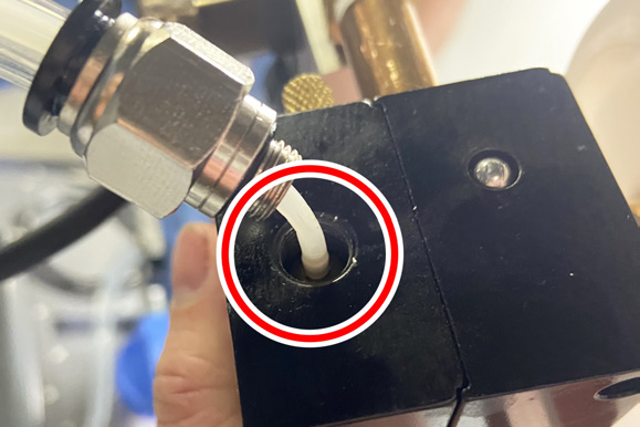
NOTE: Make sure that the tube is fully installed onto the barbed fitting. If it isn't, it may result in system performance issues.
-
Screw the push-to-connect fitting back into the pump block.
-
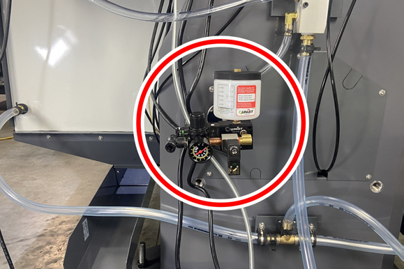
Mount the pump with its magnetic base in a convenient location. We recommend using the access panel on the back of the machine column.
-
Route the solenoid wire into the bottom of the electrical cabinet.
-
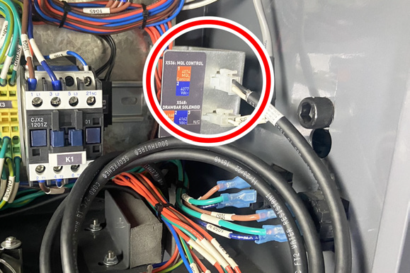
In the bottom left corner of the electrical cabinet, plug the solenoid wire into the XS36: MQL Control connector. Pull the extra wire into the electrical cabinet, coil it up, and secure it with a cable tie.
-
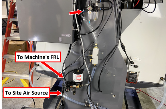
On the back of the machine, identify the air line that's connected to the machine's FRL (with the fitting installed on the end). Disconnect it from the FRL, and connect it to the inlet valve of the MQL's solenoid.
-
Identify the air line included with this kit, and connect it to the outlet valve of the MQL's solenoid. Connect the loose end of the air line to the FRL.
-
Identify the coolant included with this kit, and fill the coolant reservoir.
Looking for more information?
This is a section of the 1500MX operator's manual. To view the whole manual, go to Tormach document UM10811.
If you have additional questions, we can help. Create a support ticket with Tormach Technical Support at tormach.com/how-to-submit-a-support-ticket for guidance on how to proceed.