Before You Begin
Make sure that:
-
The machine is powered on.
-
The enclosure is installed.
Required Tools
-
1-2-3 block
-
Metric hex wrench set
-
Dial test indicator (0.0005 in. indicator or better) with magnetic base
-
Flat-blade screwdriver
Notes
Torque fasteners to the noted specification. If no specification is noted, hand tight is sufficient.
Wireless Receiver Installation
-
Identify the wireless receiver, bracket, cable, and hardware included in this kit.
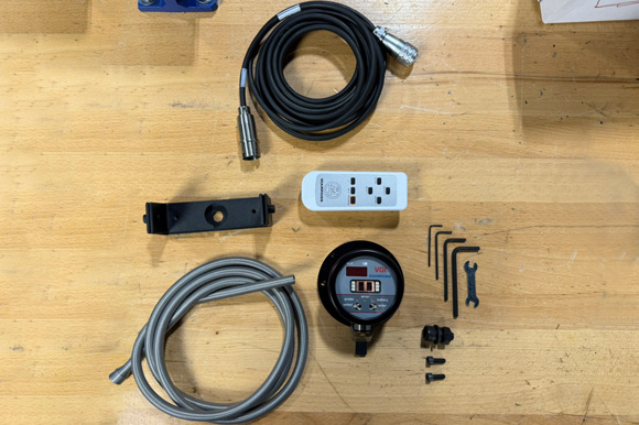
NOTE: The provided remote can be used for programming, but the receiver is already programmed. If you need assistance with programming the receiver, contact tech support.
-
You can install the wireless receiver into the enclosure in either of the following ways:
-
Use the provided bracket to mount the receiver to the enclosure panel. With this installation method, you're able to better position the receiver toward the spindle.
-
The receiver is magnetic, so you can just place it onto the enclosure. With this installation method, you have more flexibility in the placement of the receiver.
-
-
To mount the receiver with the provided bracket on the enclosure panel, first attach the bracket to the screw hole nearest to the enclosure door on the inside of the front right enclosure panel (behind the operator console) using the included hardware and a 4 mm hex wrench.
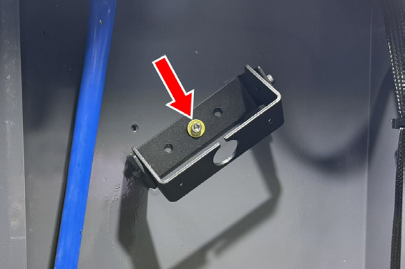
NOTE: There are two hole patterns available. You can use either of them to make sure that the probe has a good connection.
-
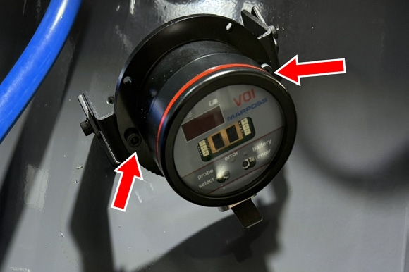
Attach the wireless receiver to the bracket using the included hardware and a 4 mm hex wrench.
-
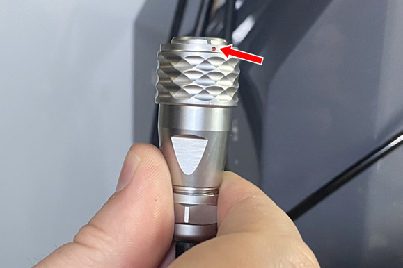
Align the pin on the cable with the pin on the receiver. Connect the cable to the receiver, and lower bracket to secure it in place.
-
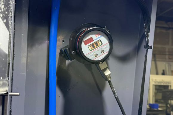
Adjust the wireless receiver’s bracket to point the receiver’s panel towards the mill’s spindle.
-
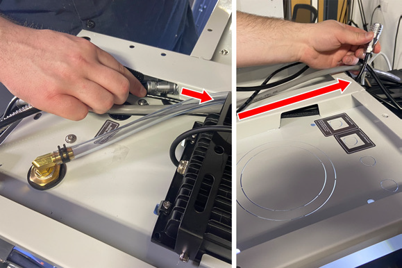
Remove the grommet on the top of the enclosure, and slide it onto the loose end of the wireless receiver's cable. Reinstall the grommet back onto the top panel of the enclosure, and pull the slack through.
-
Route the wireless receiver’s cable back towards the mill’s electrical cabinet.
-
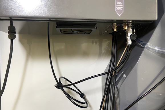
Connect the wireless receiver’s cable to the Probe Control connector on the bottom of the mill's electrical cabinet. Align the red dots on both the cable and the connector.
-
Secure the wireless receiver’s cable using zip ties.
Tool Setter Installation and Setup
-
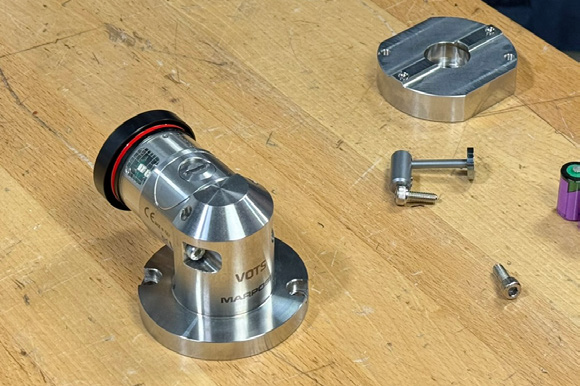
Identify the electronic tool setter included in this kit. Remove the base off of the tool setter with a 4 mm hex wrench.
-
Install the tool setter's base ring to the machine table with the provided M12 × 1.75 - 30 socket head cap screw.
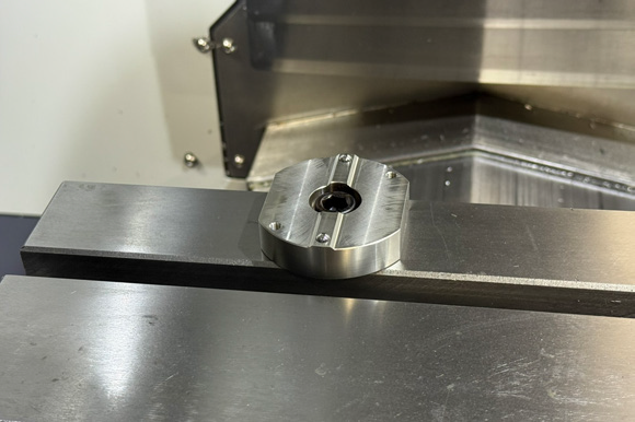
-
Place the tool setter assembly over the base ring and secure it to the base ring by tightening the set screws.
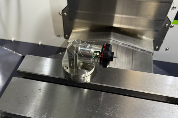
-
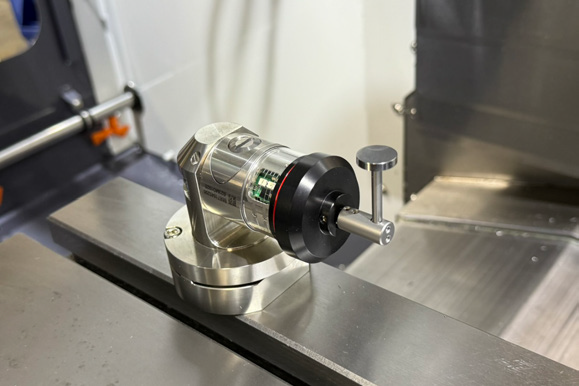
Install the stylus onto the tool setter using a 1.5 mm hex wrench.
Align the Tool Setter's Stylus
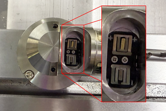
The position of the stylus is controlled by two sets of screws on the tool setter:
-
Use the lower screws to adjust the X-axis.
-
Use the upper screws to adjust the Y-axis.
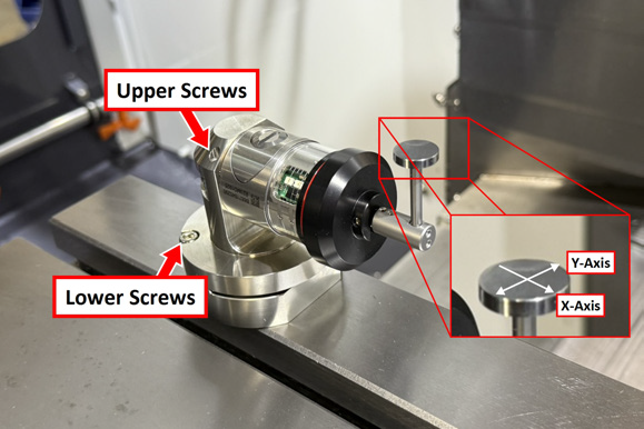
The adjustments are made completely separately from one another, but you can make them in any order. We recommend adjusting until the dial indicator shows movement of less than 0.0005 inches in both directions.
-
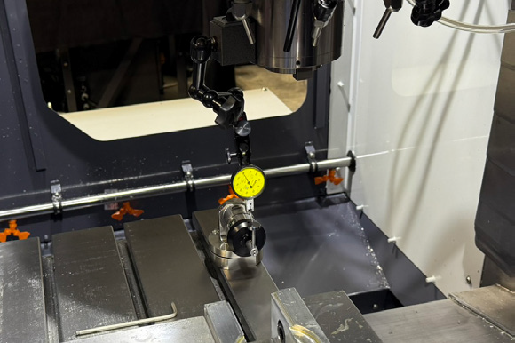
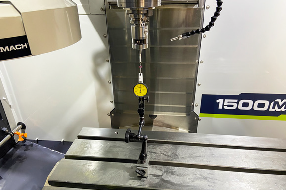
Mount a dial indicator on the spindle, and carefully jog the indicator's tip to the top of the tool setter's stylus.
-
To adjust the X-axis of the tool setter, jog the indicator's tip to either the front or the back of the stylus and set the needle to zero. You'll always check from this side.
-
Sweep the indicator to the opposite side of the stylus and watch the needle.
-
Depending on the amount of movement, adjust the lower screws on the tool setter by slightly tightening one and loosening the other.
-
Jog the indicator's tip back to the opposite side of the stylus (where you originally started). Set the needle to zero, and sweep the indicator back to the opposite side of the stylus.
-
Continue adjusting and rechecking until the reading on the dial indicator is less than 0.0005 inches.
-
To adjust the Y-axis of the tool setter, jog the indicator's tip to either the left or the right of the stylus. You don't need to reset the indicator to zero — you'll just check for movement.
-
Sweep the indicator to the opposite side of the stylus and watch the needle.
-
Depending on the amount of movement, adjust the upper screws on the tool setter by slightly tightening one and loosening the other.
-
Continue adjusting and rechecking until the reading on the dial indicator is less than 0.0005 inches.
Reference the Tool Setter
-
Remove the tool setter’s battery door using a flat-blade screwdriver or similar object.
-
Identify the two batteries included with this kit. Put both batteries into the tool setter. Replace the battery door onto the tool setter, and secure it with a screwdriver.
NOTE: Do not depress the tool setter’s stylus while inserting the batteries. Depressing the stylus will cause the tool setter to enter settings mode. If the stylus is depressed, wait one minute for the tool setter to exit settings mode.
-
Power on the machine and the PathPilot controller.
-
Turn the Main Disconnect switch to ON on the side of the electrical cabinet.
-
Twist out the machine's red Emergency Stop button, which enables movement to the machine axes and the spindle.
-
Press the Reset button.
-
Bring the machine out of reset and reference it.
-
-
If you haven't already done so, enter the diameter and length for the calibration tool (engraved on the side of the tool) into PathPilot. From the PathPilot interface, on the Offsets tab, enter details into tool 1000.
-
Load the calibration tool into the spindle. From the PathPilot interface, in the Tool DRO field, type 1000 and press the Enter key on the keyboard.
-
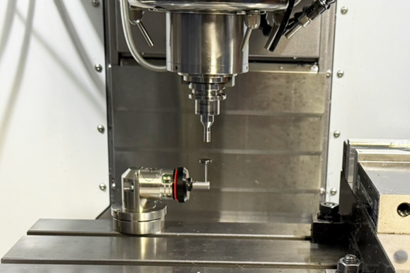
Jog the machine table so that the tool setter is under the tool, and slowly jog the Z-axis down until it's just above the tool setter.
-
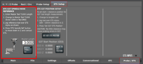
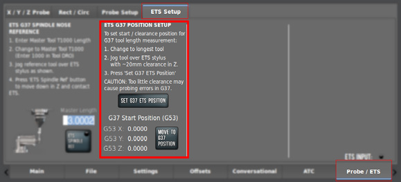
From the PathPilot interface, on the Probe/ETS tab, open the ETS Setup tab. Then, select ETS Spindle Ref.
Set G37 Position
-
Load the longest tool that you'll be using into the spindle. From the PathPilot interface, change to that tool.
-
Jog the tool so that it's about 20 mm above the tool setter's stylus.
-
From the PathPilot interface, on the ETS Setup tab, select Set G37 ETS Position.
Wireless Probe Installation and Setup
-
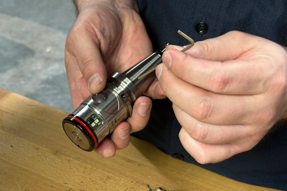
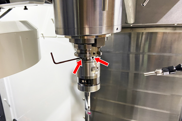
Identify the wireless probe included in this kit. Install it into the BT30 probe holder by tightening the two set screws opposite each other. Do not tighten the four-set-screw pattern at this time.
-
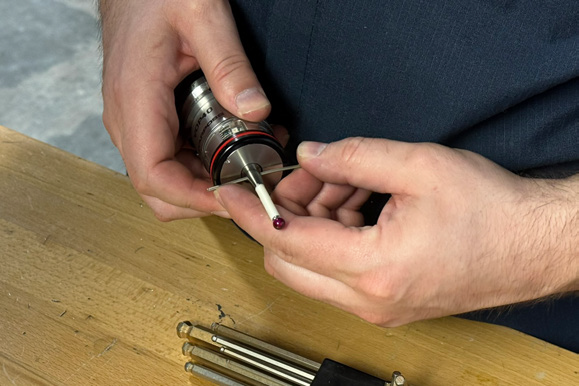
Thread the probe tip into the wireless probe.
-
Remove the probe's battery door using a flat-blade screwdriver or similar object.
-
Insert two batteries into the wireless probe. The probe lights should illuminate; if they don't, you may need to swap the battery placement.
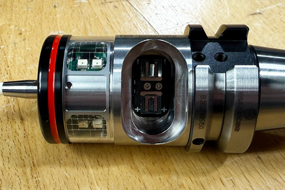
NOTE: While installing the cover, be careful not to deflect the probe tip. If you do, leave the probe for 30 seconds until the lights turn off.
-
Load the probe into the spindle.
Adjust Probe Tip Concentricity
-
Place a dial indicator on the machine table, and carefully jog the indicator's tip into the probe's tip to check for concentricity.
-
Identify the two sets of screws on the probe body. When you loosen one set screw, tighten the opposite set screw. Make adjustments as needed to the screws, manually rotate the probe by hand, and check the alignment again. Aim for the best possible concentricity, targeting between 0.0005 in. and 0.001 in.
Set Probe Length and Diameter
-
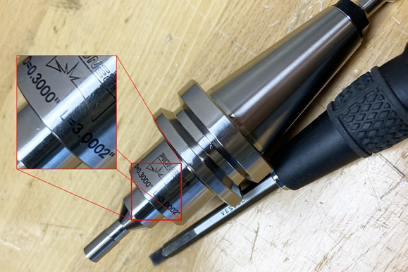
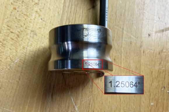
Identify the calibration tool (PN 51149) included with this kit. Load the calibration tool into the spindle. Make note of the diameter and length, which is engraved on the tool itself.
-
From the PathPilot interface, on the Offsets tab, enter the diameter and length for the calibration tool into tool 1000.
-
Wipe off the machine table.
-
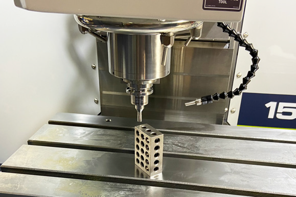
Put a 1-2-3 block on the machine table.
-
Verify that the machine is in setup mode. Use the key on the top of the operator console to switch between modes. For more information, go to “Operating Modes Reference”.
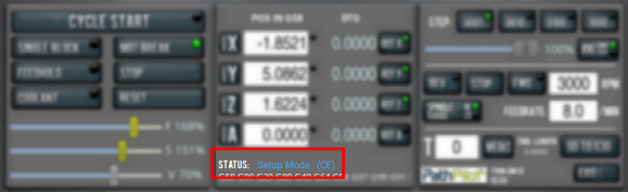
NOTE: In setup mode, you don't need to press the hold-to-run button to jog the machine with the enclosure doors open.
-
Jog the table until the block is under the calibration tool. Slowly jog the Z-axis down until it's tip drags on the 1-2-3 block.
-
Close the enclosure door.
-
From the PathPilot interface, change to T1000.
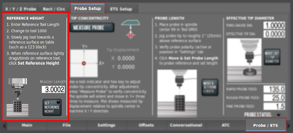
-
From the Probe/ETS tab, on the Probe Setup tab, select Set Reference Height.
-
Remove the calibration tool and load the probe into the spindle.
-
From the PathPilot interface, change to T99. Make sure the probe LED turns green. While watching the LED, flick the probe tip to make sure that the probe responds.
-
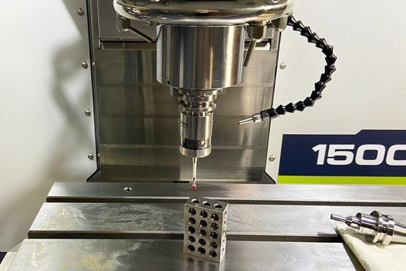
Jog the table until the 1-2-3 block is under the probe. Slowly jog the Z-axis down until the probe's tip is just above the 1-2-3 block.
-
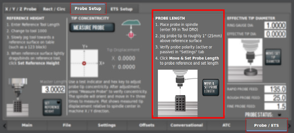
From the PathPilot interface, on the Probe/ETS tab, open the Probe Setup tab. Then, select Move and Set Probe Length.
-
Identify the ring gauge (PN 51100) included in this kit. Make note of the diameter, which is engraved on the side of the ring gauge.
-
Place the ring gauge on the machine table, and jog the spindle probe so that it's in the center of the ring gauge and 1/4 in. below the ring gauge's surface.
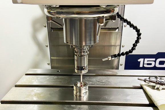
-
Close the enclosure door.
-
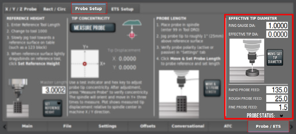
From the PathPilot interface, on the Probe tab, enter the diameter of the ring gauge into the Ring Gauge Diameter DRO field. Then, select Move/Set Tip Diameter.
Probe Status Lights Reference
|
Light |
Status |
|
Blinking green |
The probe is on and triggered |
|
Blinking red |
Error |
|
Blinking yellow |
The probe's battery signal is low |
Looking for more information?
This is a section of the 1500MX operator's manual. To view the whole manual, go to Tormach document UM10811.
If you have additional questions, we can help. Create a support ticket with Tormach Technical Support at tormach.com/how-to-submit-a-support-ticket for guidance on how to proceed.