Install the A-Axis Driver
WARNING! Electrical Shock Hazard: You must power off the machine before making any electrical connections. If you don't, there's a risk of electrocution or shock.
-
Power off the machine and the PathPilot controller.
-
Push in the machine's red Emergency Stop button, which removes power to motion control.
-
From the PathPilot interface, select Exit.
-
Turn the Main Disconnect switch to OFF on the side of the electrical cabinet.
-
-
Open the electrical cabinet door.
-
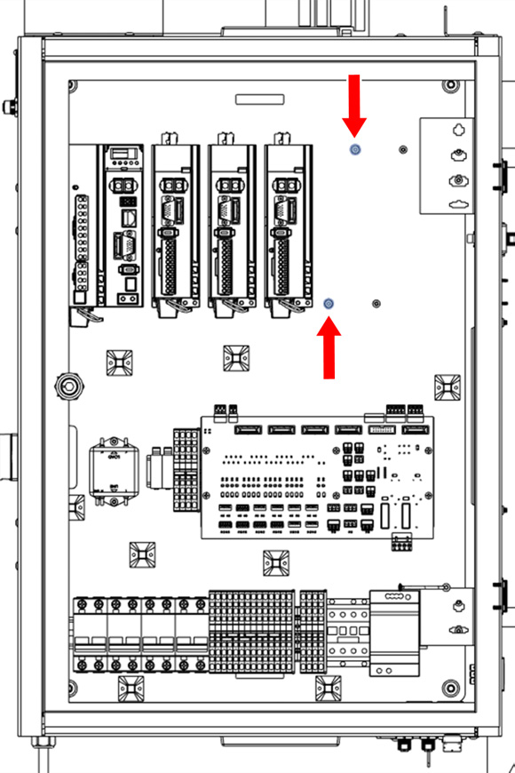
Locate the two screws next to the Z-axis driver. Remove the top screw and set it aside, and loosen the bottom screw with a 2.5 mm hex wrench.
-
Remove the ground wire from the bottom screw. You'll connect it to the A-axis driver later in this procedure.
-
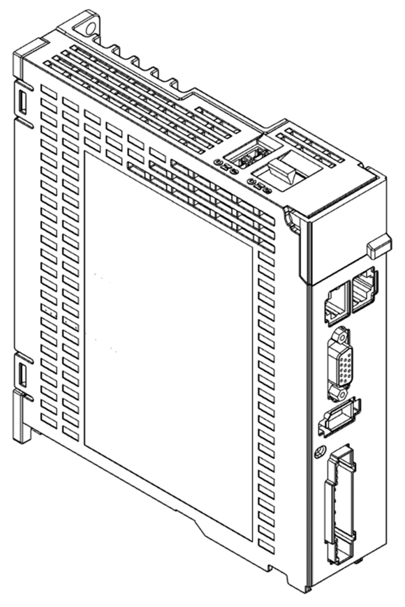
Find the A-axis driver included with this kit.
-
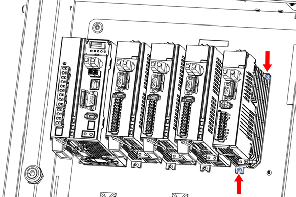
Install the A-axis driver into the electrical cabinet next to the Z-axis driver using the two screws that you identified in Step 3. Place the driver onto the loosened bottom screw and reinstall the top screw with a 2.5 mm hex wrench. Tighten both screws.
-
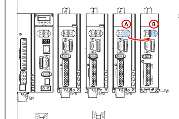
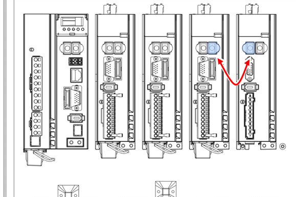
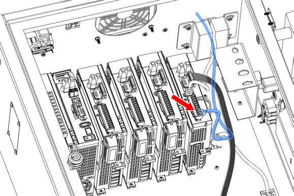
Identify the EtherCAT cable that's connected to the right port of the Z-axis driver. Disconnect the cable from the Z-axis driver and connect it to the output port on the A-axis driver.
-
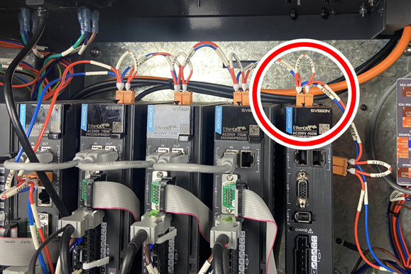
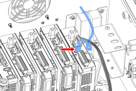
Identify the STO cable that's pre-installed in the electrical cabinet. Connect it to the A-axis driver.
-
Identify the EtherCAT jumper cable included in this kit. Connect it to both the Z-axis driver and the A-axis driver.
-
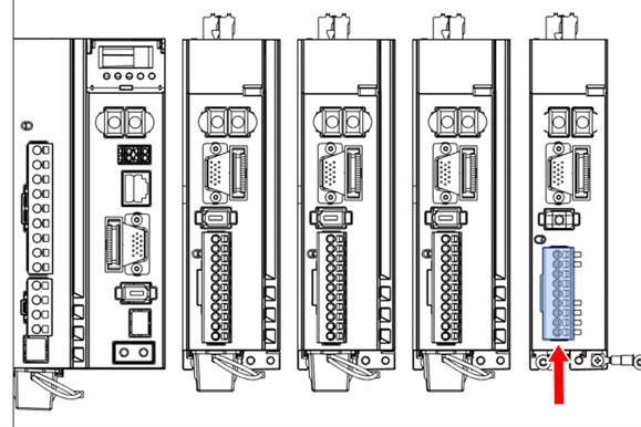
Identify the 9-pin connector that's pre-installed in the electrical cabinet's wiring harness. Connect it to the A-axis driver.
-
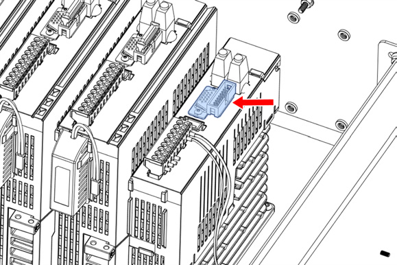
Identify the 15-pin I/O adapter provided with this kit. Connect it to the A-axis driver with both screws and a 1.5 mm hex wrench.
-
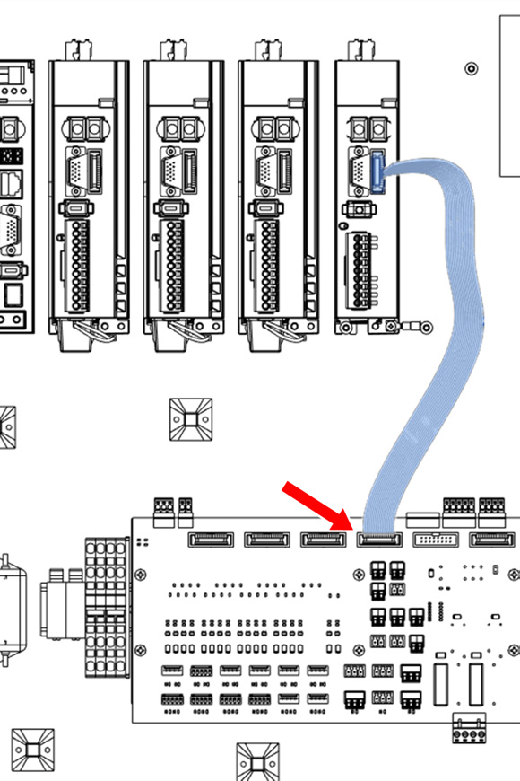
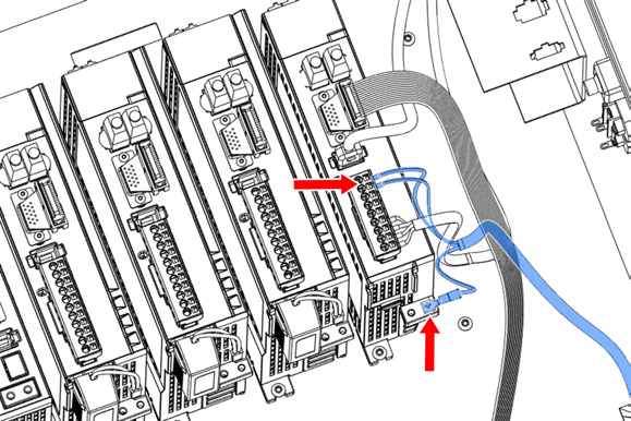
Identify the IDC ribbon cable that's included in this kit. Connect one end to the A-axis driver.
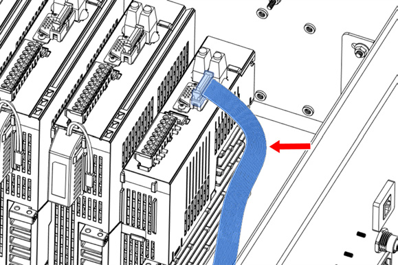
-
Connect the loose end of the IDC ribbon cable to the IDC header on the machine control board.
-
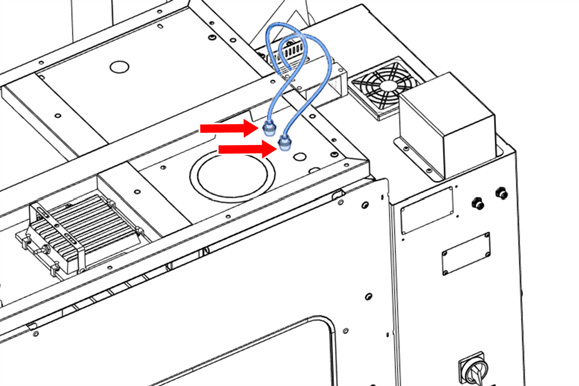
On the top right panel of the enclosure, identify the A-Axis Motor and A-Axis Encoder knockout holes. Use a hammer and punch to remove the knockouts.
-
Identify the motor and encoder cables, which are shipped connected to the microARC itself. Disconnect them.
-
Remove the nut from the bulkhead connector for the power cable (the cable with the 4-pin connector). Put it in the A-Axis Motor hole, and thread the nut onto the bottom from inside the enclosure. Repeat this step to secure the encoder bulkhead into the top panel.
-
Route the loose end of the power and encoder cable through the channel on the top of the enclosure, and toward the electrical cabinet.
-
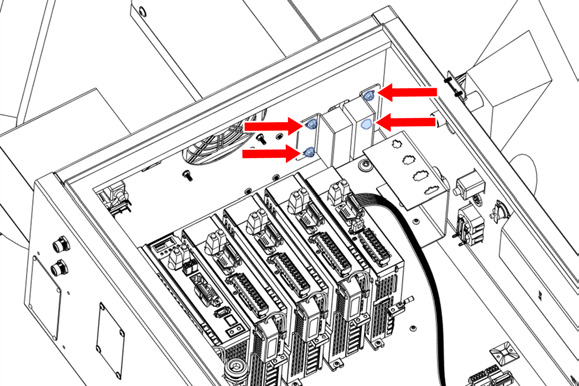
Identify the cable gland plate on the top right of the electrical cabinet. Loosen the four nuts that secure it to the cabinet, insert the encoder and power cables through the cable gland plate, and tighten the four nuts.
-
Connect the IEEE 1394 cable from the encoder to the A-axis driver.
-
On the 9-pin connector that you previously connected to the A-axis driver, connect the four motor power cables to the A-axis driver according to their labels (U, W, V, PE).
-
Identify the ground cable that you set aside previously. Connect it to the A-axis driver and tighten the Phillips screw.
Install the microARC 6 in the Machine
WARNING! Electrical Shock Hazard: You must power off the machine before making any electrical connections. If you don't, there's a risk of electrocution or shock.
-
Power off the machine and the PathPilot controller.
-
Push in the machine's red Emergency Stop button, which removes power to motion control.
-
From the PathPilot interface, select Exit.
-
Turn the Main Disconnect switch to OFF on the side of the electrical cabinet.
-
-
If you haven't yet done so, clean off the machine table.
-
Install the handle onto the microARC with the included hardware and a 6 mm hex wrench.
-
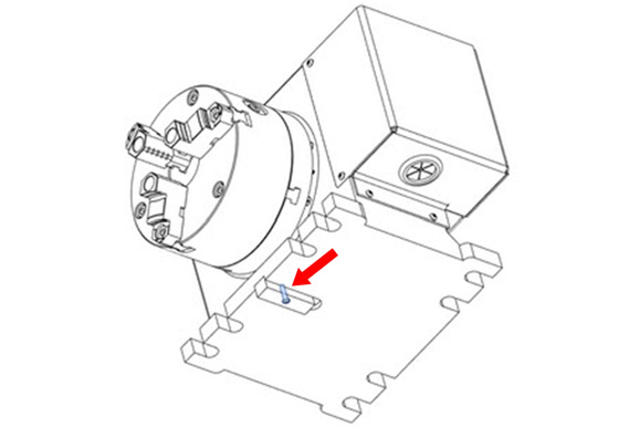
Identify the T-slot alignment pin (PN 51851) included in this kit. Install it onto the bottom of the microARC with its screw (PN 51839) and a 2 mm hex wrench.
-
Place the microARC 6 on the machine table.
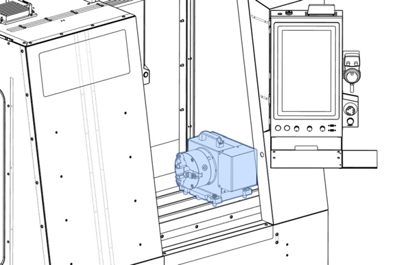
-
Secure the microARC to the machine table with the mounting hardware and a 3/8 in. hex wrench.
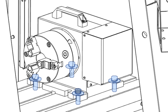
-
Connect the loose ends of the power and encoder cables to the connectors on the microARC. Align the red dot on the cable and the connector.
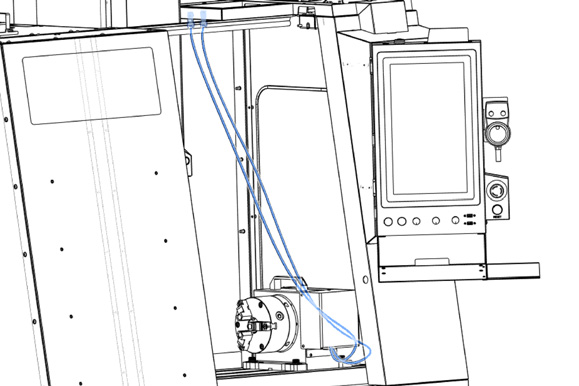
-
Power on the machine and the PathPilot controller.
-
Turn the Main Disconnect switch to ON on the side of the electrical cabinet.
-
Twist out the machine's red Emergency Stop button, which enables movement to the machine axes and the spindle.
-
Press the Reset button.
-
Bring the machine out of reset and reference it.
-
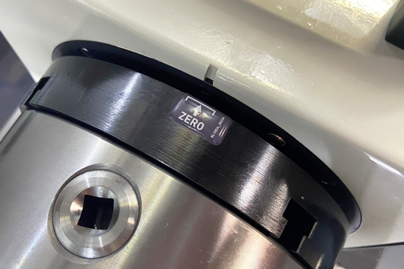
-
Manually jog the A-axis to align the reference mark on the casting within the bracket on the reference label. Once aligned, from the PathPilot interface, select Reference A-Axis.
Looking for more information?
This is a section of the 1500MX operator's manual. To view the whole manual, go to Tormach document UM10811.
If you have additional questions, we can help. Create a support ticket with Tormach Technical Support at tormach.com/how-to-submit-a-support-ticket for guidance on how to proceed.