IMPORTANT! This section is for customers who purchased the machine pre-assembled from the factory. If you are assembling the machine yourself, many of the procedures that you'll need are not included in this section. Go to “Self-Assembled Installation” for information specific to self-assembled machines.
Complete the following steps in the order listed:
Set Up the PathPilot Controller
Before operating your machine, configure in PathPilot the date, time, keyboard language.
Specify the Date and Time
-
If you haven't yet done so, turn the key on the top of the operator console into the setup mode position. You can identify which mode the controller is in by referencing the Statusread-only field.

-
From the PathPilot interface, on the Main tab, in the MDI Line DRO field, type Admin Date. Then select the Enter key.
The Time and Date Settings dialog box displays.
NOTE: Before using any ADMIN commands, you must release the Emergency Stop. Rotate the Emergency Stop button one quarter turn to release it.
-
Complete the fields in the Time and Date Settings dialog box, and then select Close.
Specify the Keyboard Language
By default, the keyboard language is set to English.
To specify a different keyboard language:
-
From the PathPilot interface, on the Main tab, in the MDI Line DRO field, type Admin Keyboard. Then select the Enter key.
The Keyboard Preferences dialog box displays. -
Select the Layouts tab and select the desired language. If the language you want is not listed, select Add to specify the language. Then, select Close.
Update PathPilot
We're constantly updating PathPilot to bring you more features. Before operating your machine, update to the latest version.
-
Confirm that the PathPilot controller is powered on and out of Reset mode.
-
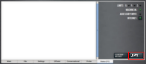
Downloading and installing an update file requires an Internet connection. From the Status tab, confirm that the Internet button LED light is on. (To configure the network, select the LED light.) Then, select Update.
-
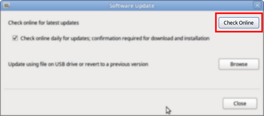
From the Software Update dialog box, select Check Online.
-
Select Install.
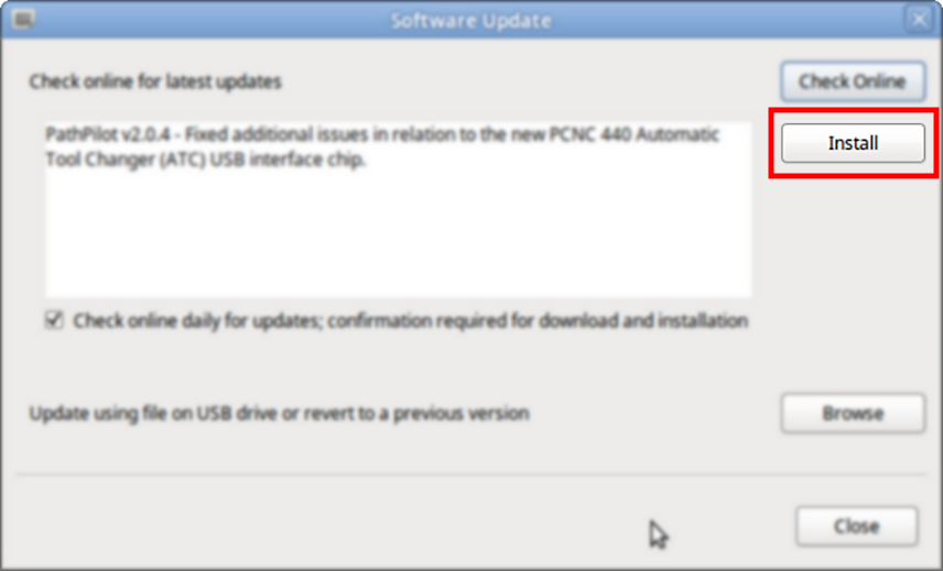
The update file is downloaded, and a notification dialog box displays.
-
From the dialog box, select OK.
The update file is installed on the PathPilot controller. -
Follow the on-screen instructions to restart the PathPilot controller.
Set Up the Automatic Oiler
Complete the following steps in the order listed:
Specify the Interval Time
The oiler distributes oil at the following times:
-
When the machine is powered on
-
After a specified interval
The interval time is the amount of time, in minutes, that the oiler waits between oil applications.
NOTE: If your machine will be unused for a long period of time (like overnight), we recommend powering off the machine to avoid over-lubricating the system.
-
Refer to "About the Automatic Oiler" for recommended interval and actuation times.
-
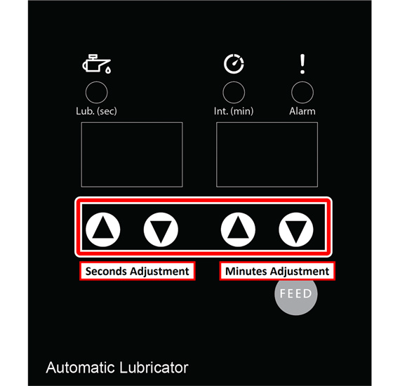
On the oiler's control panel, push and hold either of the Minutes Adjustment buttons. It doesn't matter which button you push.
The oiler beeps.
-
While looking at the Minutes display, do one of the following:
-
To increase the interval time, push the Up Arrow.
-
To decrease the interval time, push the Down Arrow.
NOTICE! Pressure Hazard: To avoid potential equipment damage, don't set the interval time to less than five minutes.
Specify the Actuation Time
The actuation time is the amount of time, in seconds, that the oiler distributes oil during an oil application.
-
Refer to "About the Automatic Oiler" for recommended interval and actuation times.
-
On the oiler's control panel, push and hold either of the Seconds Adjustment buttons. It doesn't matter which button you push.
The oiler beeps. -
While looking at the Seconds display, do one of the following:
-
To increase the interval time, push the Up Arrow.
-
To decrease the interval time, push the Down Arrow.
NOTICE! Pressure Hazard: To avoid potential equipment damage, don't set the actuation time to more than three minutes.
About the Automatic Oiler
The automatic oiler is powered whenever the machine is powered on. To prevent the excess use of oil, we recommend powering off the machine at the end of day to prevent the automatic oiler from continuing to pump oil overnight.
The automatic oiler has the following settings:
-
100% Duty Cycle
-
Lubrication interval: 480 minutes (8 hours)
NOTE: Each time the machine is powered on, it pumps oil for the amount of time equal to the actuation time. For this reason, we recommend setting the lubrication interval to 480 minutes (8 hours). This ensures that the machine has enough oil for a full eight-hour shift each time the machine is powered on. -
Actuation time: 7 seconds
-
-
75% Duty Cycle
-
Lubrication interval: 480 minutes (8 hours)
-
Actuation time: 5 seconds
-
-
50% Duty Cycle
-
Lubrication interval: 480 minutes (8 hours)
-
Actuation time: 4 seconds
-
About Actuation Time
The lubrication interval and actuation time are set from the factory for a 100% duty cycle. These settings assume the machine is running at maximum velocity 24 hours per day, 7 days per week. As a result, this tends to deliver more oil than is needed for most applications. To prevent excess usage of oil, we recommend that you adjust the actuation time of the automatic oiler to match the duty cycle that best fits your application.
When you estimate the duty cycle that best fits your application, the best indicator is the actual spindle run time for the machine during a standard eight-hour shift. Consider what percentage of that eight-hour shift the machine is running and cutting material versus the time spent for changing parts, setting up fixtures, and idle down time.
Set Up the Flood Coolant Tank
Complete the following steps in the order listed:
Required Tools
-
Hammer
-
Metric hex wrench set
-
Phillips screwdriver
-
Pliers
-
Punch
-
Thread seal tape
Unpack the Coolant Tank Crate
-
Remove the silver screws from the top and one end of the crate with a Phillips screwdriver (or an impact gun and a bit).
-
Remove the chip baskets and any cardboard boxes included in the crate. Set them all aside.
-
Remove the wooden clamps that secure one end of the coolant tank to the pallet with a Phillips screwdriver (or an impact gun and a bit).
-
Release the brake on each of the coolant tank's four casters. Slide the coolant tank out from under the wooden clamps that are still installed on the crate.
-
With an assistant, carefully lift the coolant tank from the pallet and lower it to the floor.
-
Put the chip baskets back into the coolant tank.
Install the Flood Coolant Pump
-
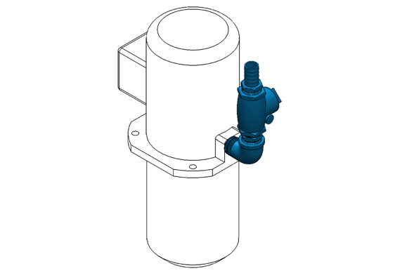
Identify the 1/4 hp flood coolant pump (PN 51384) and the elbow fitting included in this kit. Wrap the threads of the elbow fitting with thread seal tape, and hand tighten it onto the flood coolant pump.
-
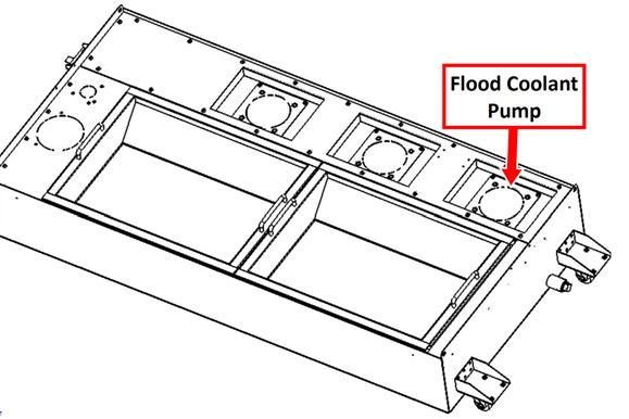
On the coolant tank, identify the location for the flood coolant pump as shown in the following image. Remove the mounting plate, and knock out the center with a hammer and punch. Then, reinstall the mounting plate onto the coolant tank.
-
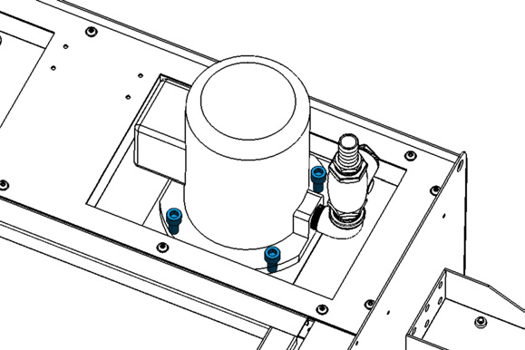
Put the coolant pump into its mounting plate. Orient the pump so that the elbow fitting is nearest to the end of the coolant tank. Secure the coolant pump to the mounting plate with four M10 × 1.5 - 20 socket head cap screws (PN 32625) and an 8 mm hex wrench.
Install the Flood Coolant Filter
-
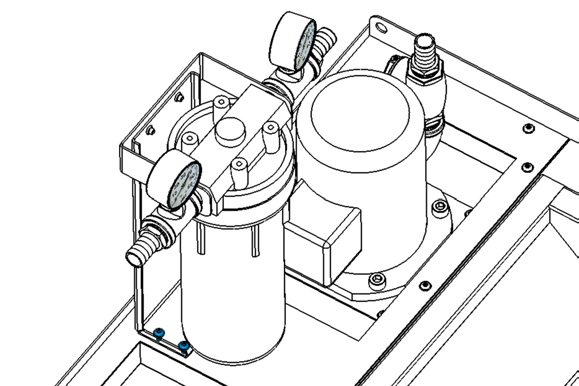
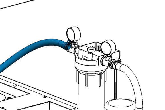
Identify the flood coolant filter included with this kit. Place it next to the flood coolant pump on the coolant tank, and secure it to the rear mounting holes with four M5 × 0.8 - 10 flanged button head cap screws (PN 38205) and a 3 mm hex wrench.
-
Identify the 1 ft long, 1 in. OD hose included with this kit. Install it between the barbed fittings on the outlet of the coolant pump and the inlet of the coolant filter with hose clamp springs (PN 51558) and a pair of pliers.
-
Move the coolant tank off to the side of the machine. You'll move it to its final location behind the machine later in this procedure.
Make Coolant Connections
-
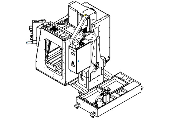
Roll the coolant tank behind the machine and push it up to the back of the machine against the base casting. Center the tank behind the machine, making sure that the chip chutes dump into the chip baskets.
-
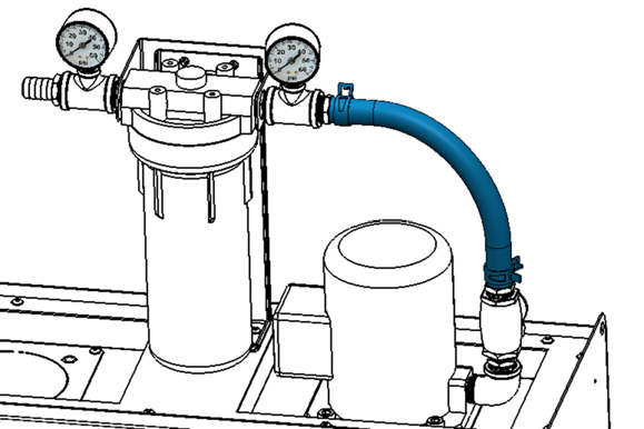
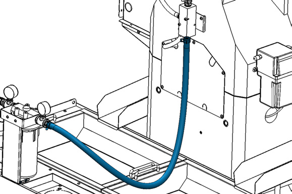
Identify the 4 ft, 1 in. OD hose (PN 51608) included with this kit. Connect one end to the barbed fitting on the outlet of the coolant filter with a pair of pliers and one hose clamp (PN 51558).
-
Connect the loose end of the hose to the barbed fitting on the bottom of the coolant manifold with a pair of pliers and one hose clamp (PN 51558).
-
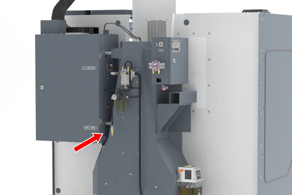
Plug the flood coolant pump's power cable into the Flood Coolant Power outlet on the side of the electrical cabinet (on the side that's closest to the column).
-
After setting up the flood coolant kit, test the enclosure for coolant leaks. Identify and seal any areas requiring extra sealant.
NOTE: If you received a factory-assembled machine, the enclosure panels may have shifted during the shipping process. It's crucial to test the enclosure for leaks even if your machine was assembled at the factory.
Looking for more information?
This is a section of the 1500MX operator's manual. To view the whole manual, go to Tormach document UM10811.
If you have additional questions, we can help. Create a support ticket with Tormach Technical Support at tormach.com/how-to-submit-a-support-ticket for guidance on how to proceed.