Required Tools
-
Adjustable torque meter, up to 20 Nm
-
Metric hex wrench set (2.5 mm, 4 mm, and 6 mm)
-
22 mm or 7/8 in. socket
-
Phillips screwdriver
-
Socket extension, 6 in. minimum
-
10 mm and 12 mm hex wrench tip with socket for ratchet torque wrench
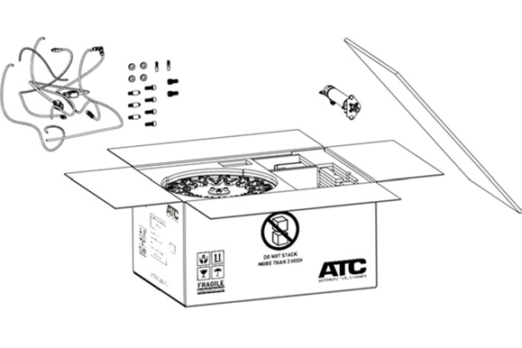
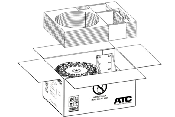
Unpack the ATC Box
-
Open the box and remove the foam cover. From the top level of foam, remove and set aside the ATC actuator assembly (PN 51856) and the ATC accessory kit (PN 53065).
-
Remove the top level of foam from the box and discard it.
-
Remove and set aside all remaining components from the box.
Prepare the Machine
-
Identify the accessory kit and the column mount assembly (PN 51857).
-
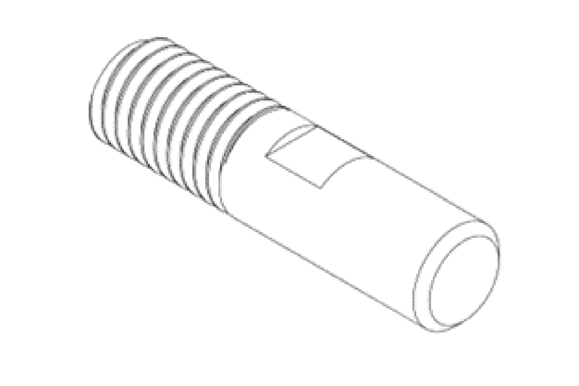
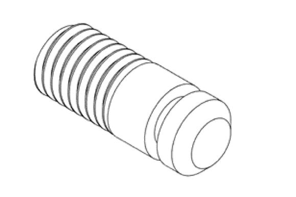
From the accessory kit, remove the two 10 mm standoffs (PN 52492).
-
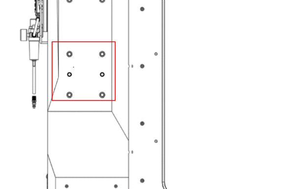
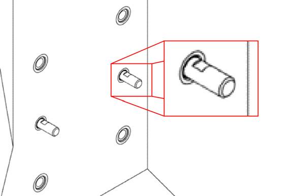
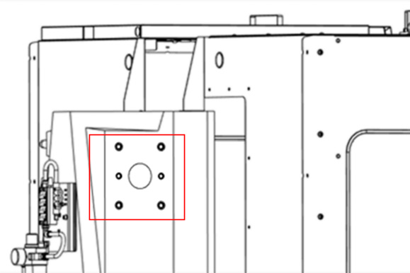
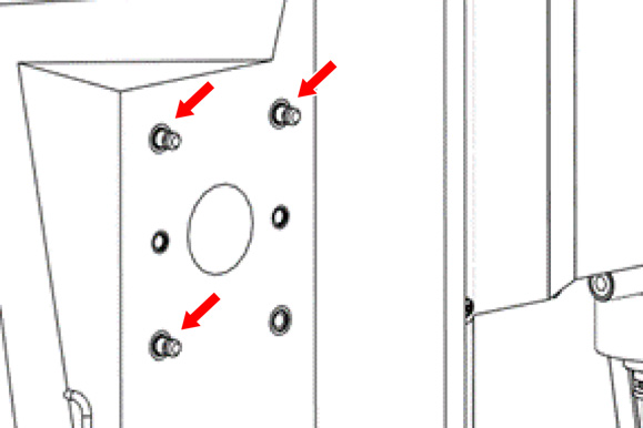
On the left side of the machine's main column mounting area, identify the six threaded inserts as shown in the following image.
-
Thread both 10 mm standoffs into the two center threaded holes as shown in the following image. Thread in the standoffs until the flats on the standoffs are flush to the column.
-
If the machine's enclosure is already installed, remove the 12 M6 × 12 flanged button head screws securing the ATC panel to the enclosure with a 4 mm hex wrench. Set the screws aside.
-
Mount the ATC column mount assembly to the column, aligning the central slots with the standoffs that you previously installed.
-
From the accessory kit, remove four M12 washers (PN 52288) and four M12 × 30 mm screws (PN 52448).
-
Secure the ATC column mount assembly to the column by screwing four M12 × 30 mm screws and four M12 washers into the remaining threaded inserts, tightening them with a 10 mm hex wrench (not included in the accessory kit). Realign the column mount if necessary and, once it's fully aligned, completely tighten the four screws.
Assemble the ATC
-
From the accessory kit, remove two M14 × 25 socket head cap screws (PN 53055) and the 12 mm hex wrench.
-
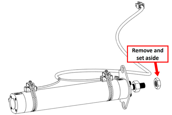
Identify the ATC actuator assembly that you set aside earlier. Unscrew the thin nut from its piston rod, and set the nut aside.
-
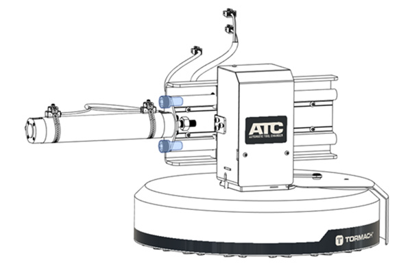
Install the ATC actuator assembly on the left side of the ATC slide assembly with two M14 × 25 socket head cap screws and a 12 mm hex wrench.
-
Slide the motor box toward the piston until the motor box bracket fits into the piston rod. Secure the motor box to the piston rod using the thin nut that you set aside in Step 2. Tighten the lock nuts finger-tight for now.
-
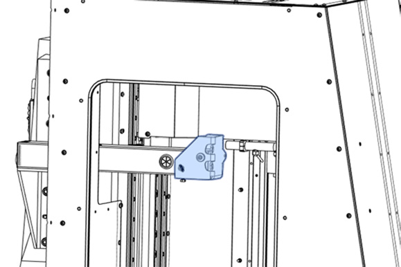
Identify the ATC tilt bracket on the column mount assembly. Remove the bracket from the assembly by removing the M8 × 100 and M8 × 12 socket head cap screws and their washers with a 6 mm hex wrench. Set aside the fasteners.
-
From the accessory box, remove three M8 × 1.25 - 12 screws (PN 50578) and three flat washers (PN 30531). Attach the tilt bracket to the ATC's slide plate with the three screws, three washers, and a 6 mm hex wrench. Loosen the M8 hex head screw at the bottom of the ATC tilt bracket if necessary.
-
Push the actuator in to close the carousel's door.
-
Using the fasteners that you set aside in Step 5, attach the ATC to the column mount assembly that's installed on the machine with a 6 mm hex wrench.
Install the ATC Electrical Cabinet
-
From the accessory kit, remove three M12 × 15 mm standoffs (PN 51974).
-
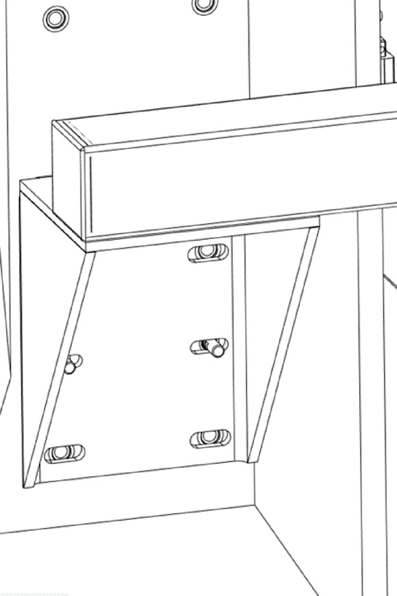
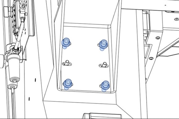
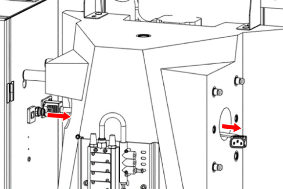
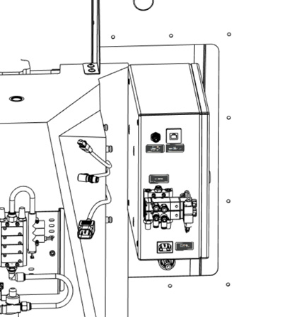
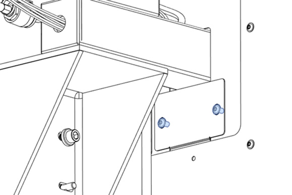
On the left side of the machine's main column mounting area, identify the upper arrangement of threaded inserts as shown in the following image.
-
Thread the three M12 × 15 mm standoffs into the threaded holes as shown in the following image.
-
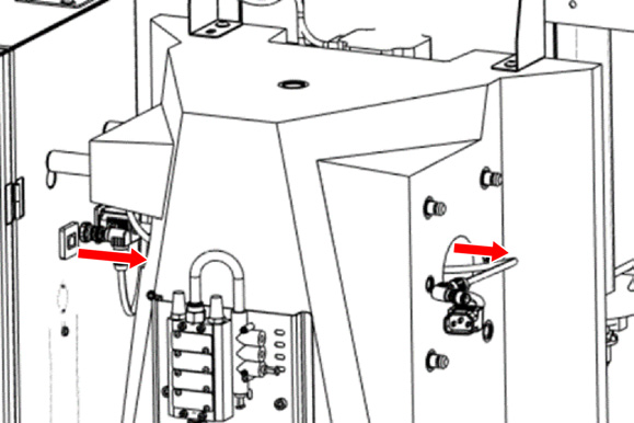
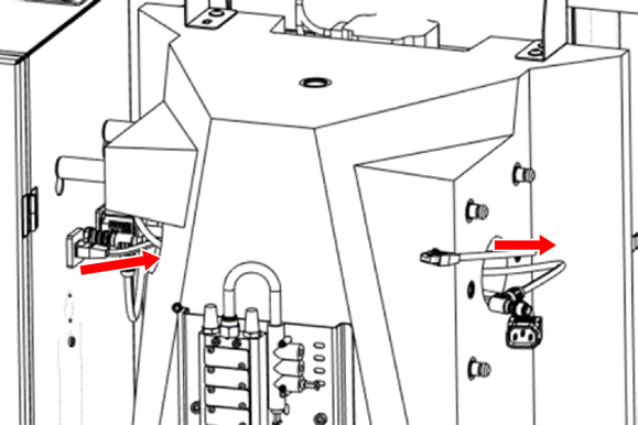
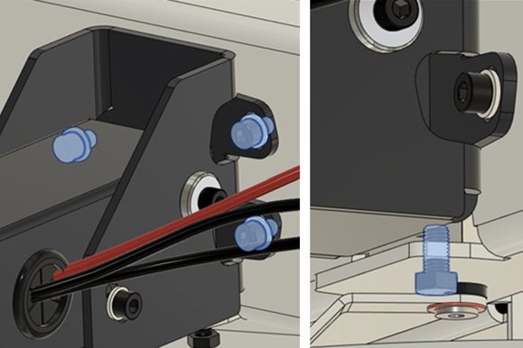
Connect the black IEC cable (PN 51969) to the ATC Power connector on the right side of the machine's electrical cabinet. Bring the cable through the column as shown in the following image.
-
Connect the EtherCAT cable (PN 51970) to the ATC Communication connector on the right side of the machine's electrical cabinet. Bring the cable through the column as shown in the following image.
-
Connect the ATC STO cable (PN 51965) to the ATC STO connector on the right side of the machine's electrical cabinet. Bring the cable through the column as shown in the following image.
-
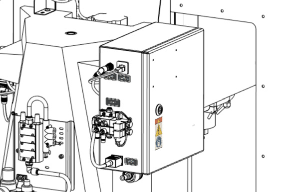
Identify the ATC electrical cabinet (PN 51949). Align its three keyhole slots on the back with the three standoffs previously installed on the machine's column. Once the standoffs fit into the cabinet's slots, let the weight of the cabinet guide the standoffs into the narrow part of the slot. Adjust the cables so that they don’t get pinched.
-
Connect the loose ends of the IEC cable, the EtherCAT cable, and the ATC STO cable to the ATC Power, ATC Communication, and ATC STO connectors on the outer left side of the ATC's electrical cabinet.
-
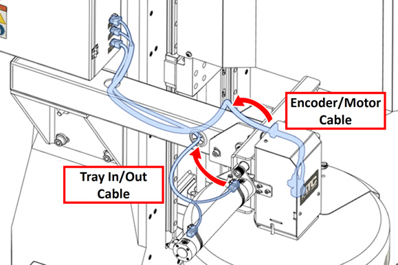
Identify the loose end of the encoder/motor power cable and the tray in/out cable that are pre-installed on the ATC. Route the loose ends of the cables as follows:
-
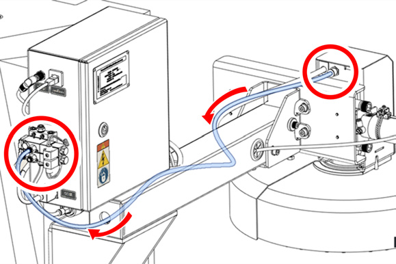
Route the encoder/motor power cable (PN 51967) through the grommet on the right side of the ATC column mount and out through the upper hole on the arm.
-
Route the tray in/out cable (PN 51966) through the grommet on the left side of the ATC column mount and out through the upper hole on the arm.
-
c. Connect the loose ends of the cables to the ATC Tray Position Sensor, ATC Motor Encoder, and ATC Motor Power connectors on the outer right side of the ATC's electrical cabinet.
-
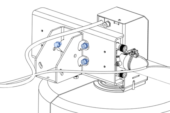
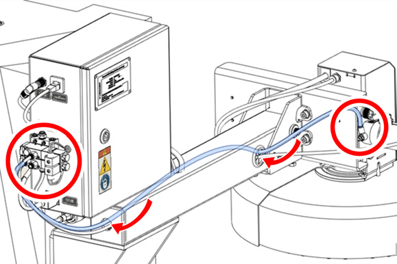
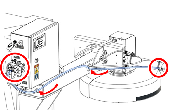
Identify the air line labeled Blaster. Connect one end of the air line to the rear of the ATC's motor box. Route the loose end as follows:
-
Route the air line through the grommet on the right side of the ATC column mount and out through the plug in the rear hole on the arm.
-
Connect the loose end of the air line to the right port of the upper solenoid valve on the ATC's electrical cabinet.
-
-
Identify the air line labeled Tray In. Connect one end of the air line to the fitting on the ATC actuator assembly that's closest to the motor box. Route the loose end as follows:
-
Route the air line through the grommet on the left side of the ATC column mount and out through the plug in the rear hole on the arm.
-
Connect the loose end of the air line to the left port of the lower solenoid valve on the ATC's electrical cabinet.
-
-
Identify the air line labeled Tray Out. Connect one end of the air line to the fitting on the ATC actuator assembly that's furthest from the motor box. Route the loose end as follows:
-
Route the air line through the grommet on the left side of the ATC column mount and out through the plug in the rear hole on the arm.
-
Connect the loose end of the air line to the right port of the lower solenoid valve on the ATC's electrical cabinet.
-
-
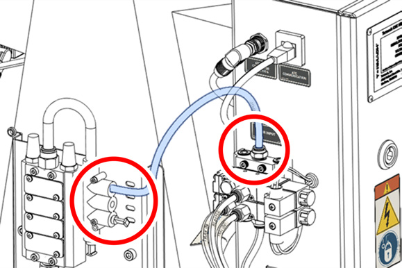
Identify the air line labeled Air Input. Connect one end of the air line to the upper (main) fitting of the ATC's pneumatic distributor, and connect the loose end to the upper port of the machine's pneumatic distributor.
-
Depending on your machine configuration, do one of the following:
-
Enclosure Installation Completed:
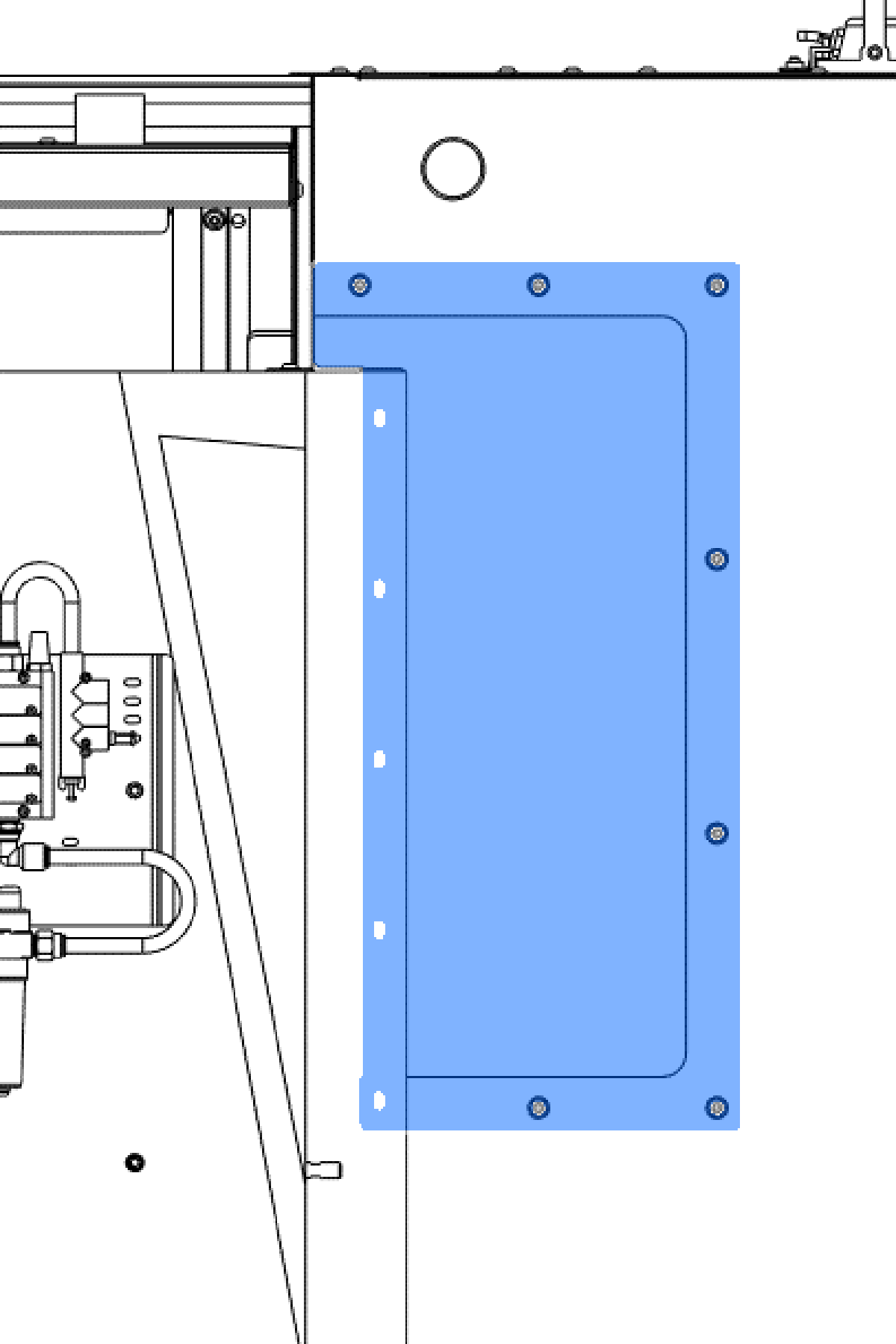
a. Fasten the ATC mount cover panel (PN 52374) to the left rear panel using 12 M6 × 1.0 - 12 screws.
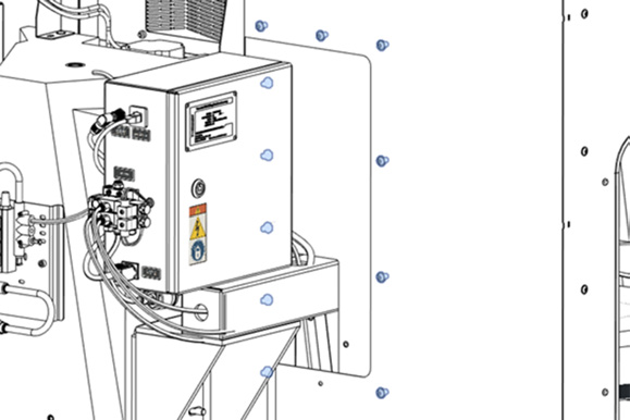
b. Identify the mount gap plate (PN 52450). Install it from the outside of the left rear panel using two M6 × 12 flanged button head screws.
-
Enclosure Installation in Progress: Return to Install the Enclosure to complete the enclosure installation. Start with the section to install the enclosure panels.
Level and Align the ATC
Required Tools
-
Adjustable torque meter up to 20 Nm
-
6 mm hex tip for ratchet torque wrench
-
Precision square
-
Ratchet with 22 mm socket
-
Wrench
-
Phillips screwdriver
-
BT30 tool holders
-
1/2 in. collet for BT30 tool holder
-
1/2 in. rod
-
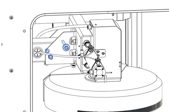
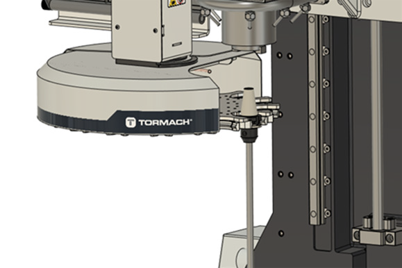
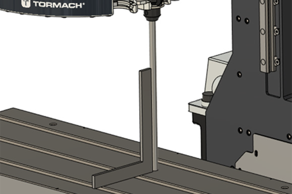
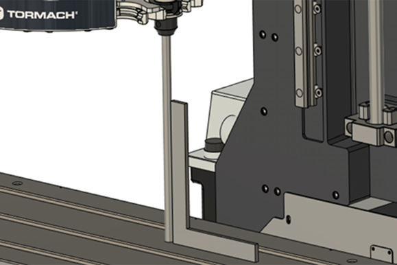
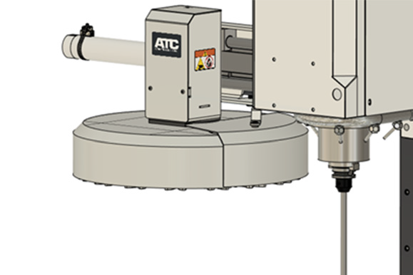
Disconnect the air from the machine, and manually move the ATC to its tool change position (if the spindle interferes, power on the machine and jog the spindle to its highest position, and then power off the machine). Mount a tool holder with a 1/2 in. rod in the slot of the tool tray closest to the spindle, as shown below.
-
Put the precision square on the machine table so that it's standing on its short end and aligned along the Y-axis (perpendicular to the table slots).
-
Adjust the tilt of the ATC along the X-axis:
-
Slightly loosen the three M8 screws on the mounting assembly and turn the bottom jack screw with a wrench.
-
b. Repeat Step A until the rod is perfectly parallel with the precision square.
c. Retighten the three M8 screws, adjusting with a ratchet torque wrench with a 6 mm hex tip.
-
Turn the precision square so that it's aligned along the X-axis (parallel to the table slots).
-
Adjust the tilt of the ATC along the Y-axis:
-
Slightly loosen the three M8 screws that connect the tilt bracket and the side plate, and turn the lower jack screw with a wrench.
-
b. Repeat Step A until the rod is perfectly parallel with the precision square.
c. Retighten the three M8 screws, adjusting with a ratchet torque wrench with a 6 mm hex tip.
-
Remove the precision square from the machine table and set it aside.
-
Manually move the ATC to its retracted position, and disconnect the EtherCAT communication cable from the ATC's electrical cabinet.
-
Power on the machine and the PathPilot controller.
-
Turn the Main Disconnect switch to ON on the side of the electrical cabinet.
-
Twist out the machine's red Emergency Stop button, which enables movement to the machine axes and the spindle.
-
Press the Reset button.
-
Bring the machine out of reset and reference it.
-
-
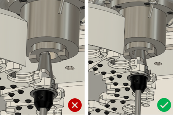
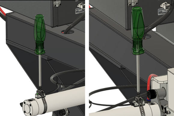
Manually move the ATC to its tool change position (with the piston fully extended), and slowly jog the spindle over the tool holder. Stop jogging just before contacting the tool holder. If the tool tray is offset, press the Emergency Stop button, and manually rotate the tool tray until it's aligned.
-
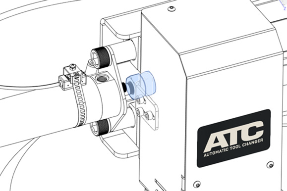
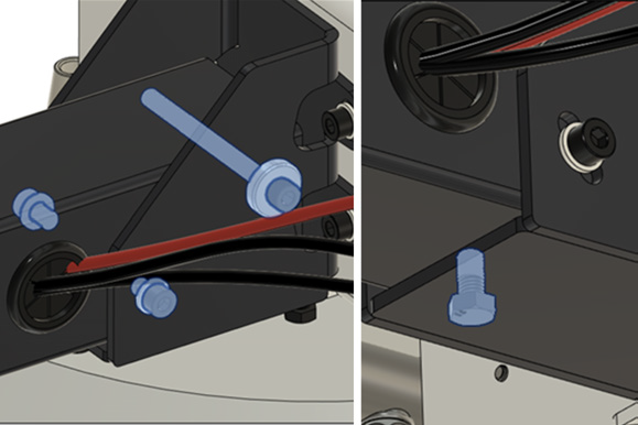
Verify the X alignment of the ATC. Depending on the deviation in the tool on the X-axis with respect to the spindle center, move the M14 fine thread piston rod nuts surrounding the connection bracket of the motor box with your fingers, and move the ATC until the tool holder is perfectly aligned with the spindle in the tool change position (with the piston fully extended). Tighten both nuts with your fingers.
-
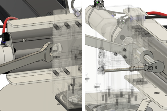
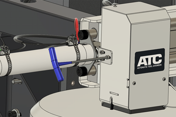
Jog the spindle up, manually move the ATC to an intermediate position, and tighten the two M14 fine thread nuts of the actuator stem between them as locknuts, with a wrench (holding the nut closest to the piston) and a ratchet with a 22 mm or 7/8 in. socket mounted on it with an extension (turning and tightening the nut furthest from the piston) as shown below.
-
Manually move the ATC in and out from end-to-end on the actuator rod travel, and ensure that both the actuator sensors light up at the travel limits. If the sensors don't light up, adjust the position of the sensor by loosening the clamp screw, adjusting, and then retightening with a Phillips screwdriver.
-
If moving the ATC outward manually feels forced, the motor box bracket may be flexing the piston rod. Bring the ATC to its retracted position, and loosen the three M5 × 10 socket screws that hold the bracket to the motor box. When the bracket has settled on its own, retighten the screws. If the ATC movement feels smooth, go to the next step.
-
Power off the machine and the PathPilot controller.
-
Push in the machine's red Emergency Stop button, which removes power to motion control.
-
From the PathPilot interface, select Exit.
-
Turn the Main Disconnect switch to OFF on the side of the electrical cabinet.
-
-
Wait for 8 seconds, and then reconnect the EtherCAT communication cable to the ATC electrical cabinet.
-
Power on the machine and the PathPilot controller.
-
Turn the Main Disconnect switch to ON on the side of the electrical cabinet.
-
Twist out the machine's red Emergency Stop button, which enables movement to the machine axes and the spindle.
-
Press the Reset button.
-
Bring the machine out of reset and reference it.
-
-
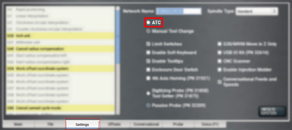
Verify that, in the PathPilot interface, the ATC tab displays.
-
If the tab doesn't display, verify that the machine is in setup mode. Use the key on the top of the operator console to switch between modes.
-
From the Settings tab, select the ATC radio button.
-
Remove the tool holder from the tool tray, and manually move the ATC to its retracted position.
-
Reconnect the pressurized air to the machine (the ATC shouldn't move), and load the tool holder into the spindle. Disconnect the pressurized air from the machine.
-
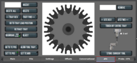
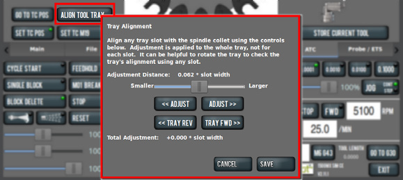
Jog the spindle down and manually bring the ATC closer to its tool change position, without directly contacting the tool holder to the tray. From the PathPilot interface, on the ATC tab, select Align Tool Tray.
-
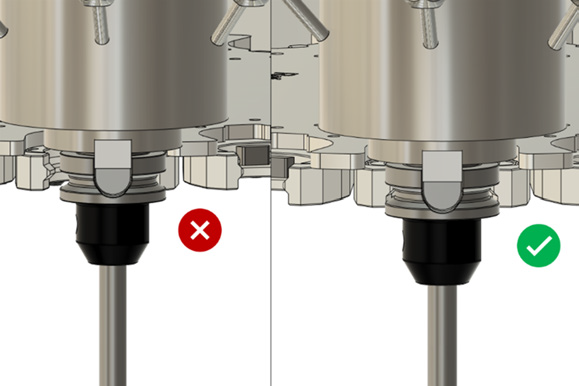
In the Tray Alignment dialog box, use the controls to rotate the tool tray until the tool holder is perfectly aligned vertically with the spindle. Once finished, select Save.
NOTE: If the machine isn't in setup mode, the controls in the Tray Alignment dialog box won't work. Use the key on the top of the operator console to switch between modes.
-
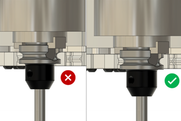
Jog the spindle up or down so that the tool holder slot is horizontally aligned within the tool tray slot. Verify this by manually moving the ATC, ensuring that the tool tray's slot contacts the tool holder in the spindle, as if you were going to make a tool change. If the movement feels strained, or if you notice the tool tray flexing up or down while doing this, manually remove the ATC from the tool holder, and readjust the height of the spindle by jogging the Z-axis.
-
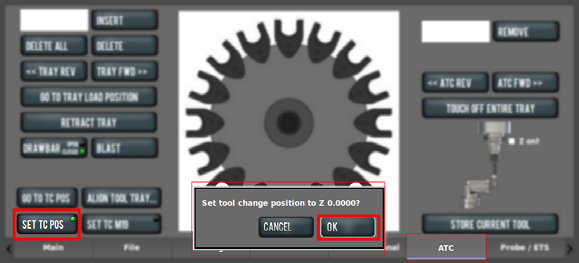
From the PathPilot interface, on the ATC tab, select Set TC POS, and then select OK.
The height at which the spindle makes tool changes is saved.
-
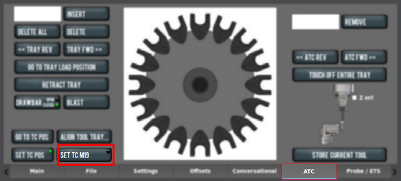
Manually move the ATC to its retracted position. From the PathPilot interface, on the ATC tab, select Set TC M19.
-
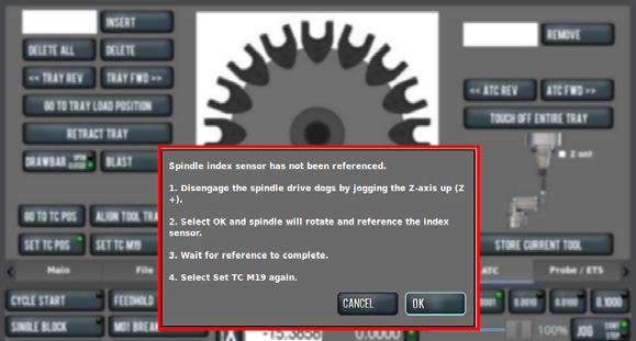
If the spindle hasn't previously been referenced, a dialog box displays with instructions to reference the spindle index sensor. Select OK, and wait for the spindle to rotate a few times to adjust the encoder.
-
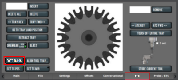
From the PathPilot interface, on the ATC tab, select Go to TC POS
The spindle lowers to its tool change position.
-
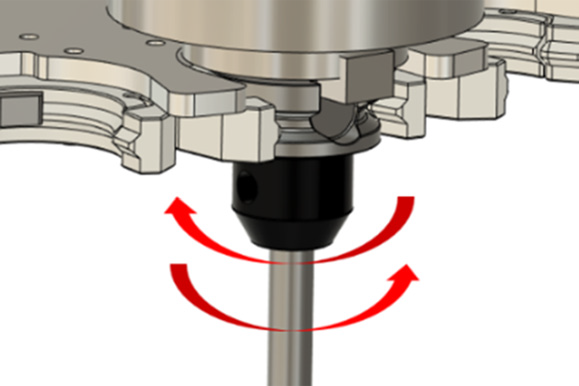
Manually move the ATC so that the tool tray holds the tool that's loaded into the spindle. From the PathPilot interface, on the ATC tab, select Set TC M19 and, from the dialog box that displays, follow the instructions to rotate the tool holder clockwise and counterclockwise to define the central position of the tool holder within the tool tray's slot.
-
Manually move the ATC to its retracted position, and jog the spindle up. Reconnect pressurized air to the machine, and remove the tool holder with the rod shaft from the spindle.
The ATC is calibrated and is ready to perform a test tool change.
Test Tool Changes
-
Load an empty tool holder into the spindle. From the PathPilot interface, in the Tool DRO field, assign a tool number (for example, 1). Then, press Enter on the keyboard.
-
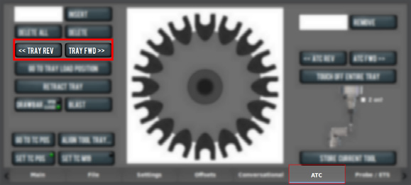
From the ATC tab, select Tray Rev or Tray Fwd to rotate the tool tray to an empty slot.
-
Select Store Current Tool.
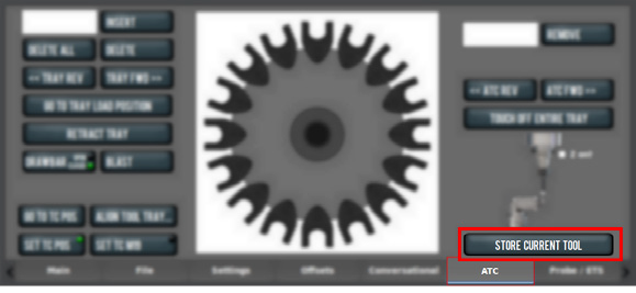
The spindle lowers, and the ATC moves to store the tool in the assigned holder.
If the tool didn't store smoothly, or if there was any sound or collision, disconnect the air from the machine and locate the exact point and reason for the collision, and verify the adjustment and alignment of the critical points mentioned earlier in this procedure.
-
From the PathPilot interface, in the Tool DRO field, type the tool number that you previously assigned (in our example, 1). Then, press Enter on the keyboard. In the dialog box that displays, select Yes.
The ATC moves, and the spindle lowers to grab the selected tool.
If the tool wasn't gripped smoothly, or if there was any sound or collision, disconnect the air from the machine and locate the exact point and reason for the collision, and check the adjustment and alignment of the critical points mentioned earlier in this procedure. -
Repeat the steps in this section, adding more tools and making more changes between them, to completely verify the operation of the ATC.
Looking for more information?
This is a section of the 1500MX operator's manual. To view the whole manual, go to Tormach document UM10811.
If you have additional questions, we can help. Create a support ticket with Tormach Technical Support at tormach.com/how-to-submit-a-support-ticket for guidance on how to proceed.