Required Tools
-
13 mm wrench
-
17 mm wrench
-
30 mm wrench
-
32 mm wrench
-
Hammer
-
Metric hex wrench set
-
Painter's tape
-
Phillips screwdriver
-
Pliers
-
Punch
-
Thread seal tape
Unpack the Coolant Tank Crate
-
Remove the silver screws from the top and one end of the crate with a Phillips screwdriver (or an impact gun and a bit).
-
Remove the chip baskets and any cardboard boxes included in the crate. Set them all aside.
-
Remove the wooden clamps that secure one end of the coolant tank to the pallet with a Phillips screwdriver (or an impact gun and a bit).
-
Release the brake on each of the coolant tank's four casters. Slide the coolant tank out from under the wooden clamps that are still installed on the crate.
-
With an assistant, carefully lift the coolant tank from the pallet and lower it to the floor.
-
Put the chip baskets back into the coolant tank.
Install the Flood Coolant Pump
-
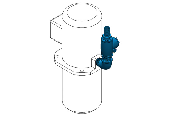
Identify the 1/4 hp flood coolant pump (PN 51384) and the elbow fitting included in this kit. Wrap the threads of the elbow fitting with thread seal tape, and hand tighten it onto the flood coolant pump.
-
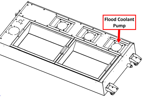
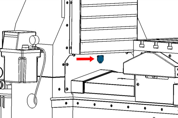
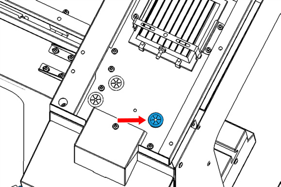
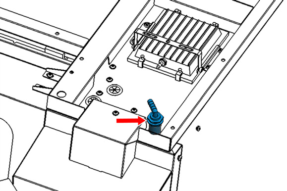
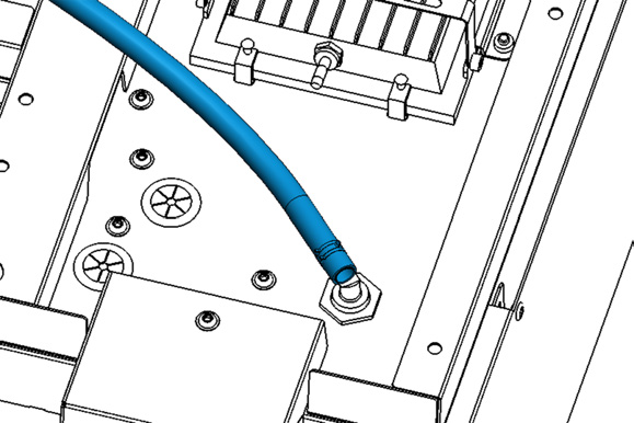
On the coolant tank, identify the location for the flood coolant pump as shown in the following image. Remove the mounting plate, and knock out the center with a hammer and punch. Then, reinstall the mounting plate onto the coolant tank.
-
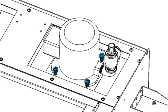
Put the coolant pump into its mounting plate. Orient the pump so that the elbow fitting is nearest to the end of the coolant tank. Secure the coolant pump to the mounting plate with four M10 × 1.5 - 20 socket head cap screws (PN 32625) and an 8 mm hex wrench.
Install the Flood Coolant Filter
-
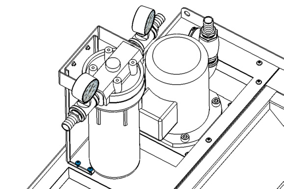
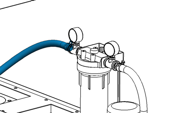
Identify the flood coolant filter included with this kit. Place it next to the flood coolant pump on the coolant tank, and secure it to the rear mounting holes with four M5 × 0.8 - 10 flanged button head cap screws (PN 38205) and a 3 mm hex wrench.
-
Identify the 1 ft long, 1 in. OD hose included with this kit. Install it between the barbed fittings on the outlet of the coolant pump and the inlet of the coolant filter with hose clamp springs (PN 51558) and a pair of pliers.
-
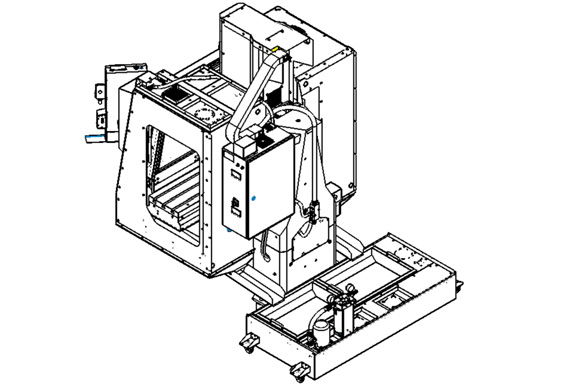
Move the coolant tank off to the side of the machine. You'll move it to its final location behind the machine later in this procedure.
Install the Coolant Manifold
-
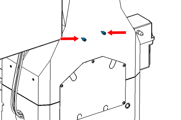
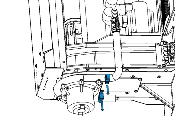
On the back of the machine column, identify the bottom set of M6 threaded inserts. Identify two standoffs (PN 51566) included with this kit. Then, install and tighten them into the back of the machine column with a 13 mm wrench.
-
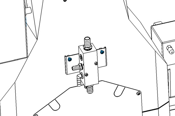
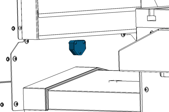
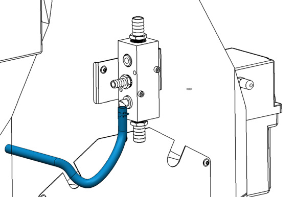
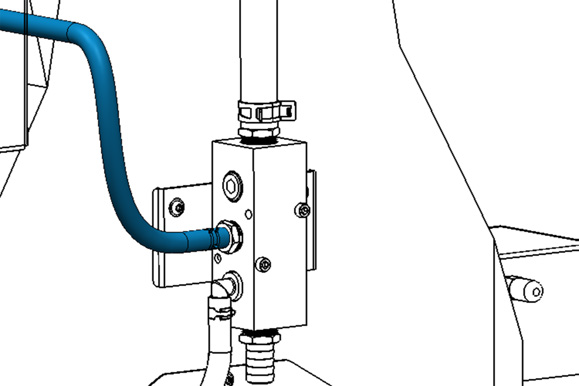
Identify the coolant manifold assembly (PN 51565) and two M6 × 1 - 10 flanged button head cap screws (PN 51616) included with this kit. Secure the manifold to the standoffs with a 4 mm hex wrench. Make sure that the manifold is oriented with the mounting screws toward the top of the machine.
Install the Y-Axis Washdown Nozzle
-
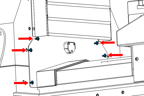
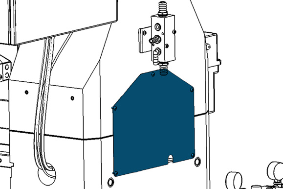
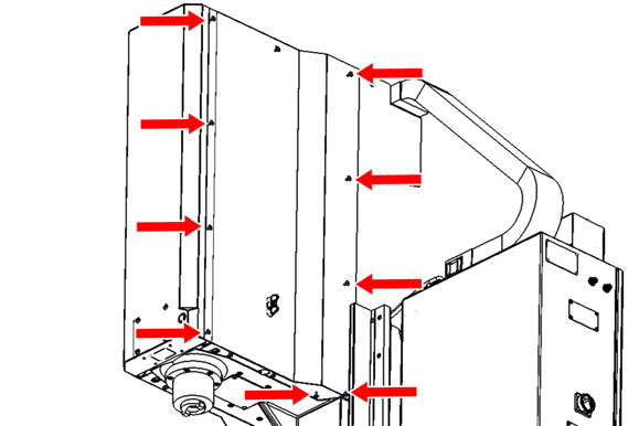
On the front of the machine, identify the Y-axis rear way cover. Remove and set aside the six M6 screws securing the Y-axis rear way cover to the column with a 4 mm hex wrench. Slide the cover toward the table to gain access to the back of the cover.
-
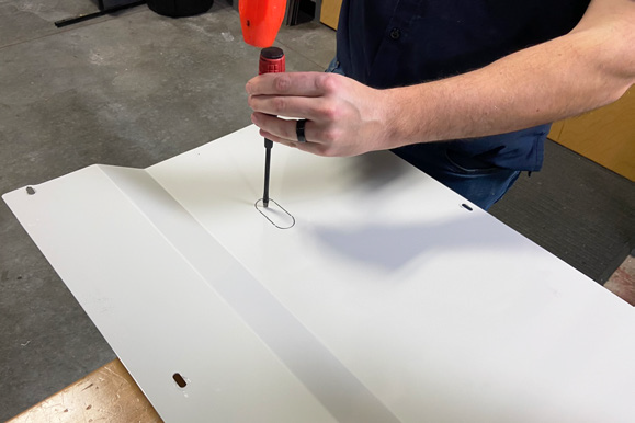
Remove the three M4 screws that secure the cover plate onto the way cover with a 2.5 mm hex wrench. Discard the screws and the cover plate.
-
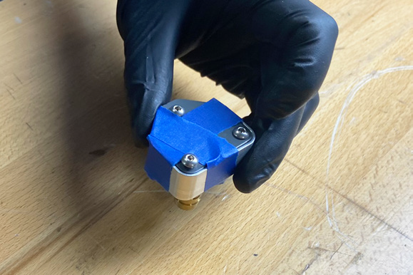
Identify the Y-axis washdown block that's included in this kit.
IMPORTANT! The Y-axis washdown block contains 3 very small O-rings. Pay attention and use care when handling to prevent dropping or losing the O-rings. We recommend taping the assembly together to prevent the cover plate from falling off while you're installing the block onto the machine.
-
Tape the washdown block assembly together. Then, remove the three hex nuts from the back of the washdown block with a 2.5 mm hex wrench and a 7 mm wrench. Do not remove the screws from the block because these help hold the O-rings in place. The nuts are for shipping purposes and can be discarded.
-
Install the washdown block on the front of the Y-axis cover with its three pre-installed screws and a 2.5 mm hex wrench. Remove the painter's tape from the washdown block.
-
Re-install the Y-axis rear way cover to the column of the machine with the six M6 screws that you set aside earlier.
-
On the back of the machine, identify the rear access panel. Remove the five M6 screws from the panel and set the screws aside.
-
Knock out the upper left knock-out on the access panel with a hammer and punch.
-
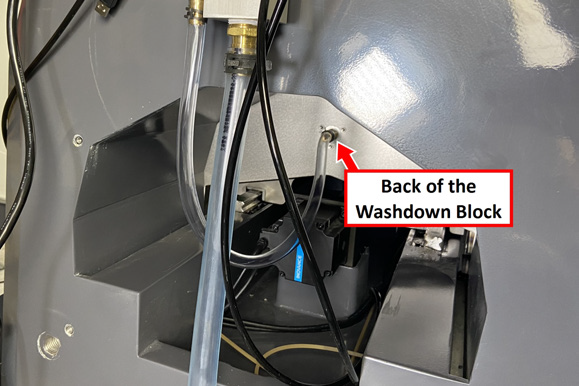
Identify the 20 in. long, 5/8 in. OD hose (PN 51516) included in this kit. From the back of the machine, install the hose to the 1/2 in. barbed hose fitting on the back of the washdown block with one hose clamp (PN 51679) and a pair of pliers.
-
Route the loose end of the hose through the knock-out in the access panel, and re-install the access panel onto the back of the machine with the five M6 screws that you set aside earlier.
-
Install the loose end of the hose onto the 1/2 in. barbed elbow fitting on the coolant manifold with a hose clamp (PN 51679) and a pair of pliers.
Install the Flood Coolant Ring
-
On the front of the machine, remove the nine M6 flanged button head cap screws on the side of the right side spindle cover with a 4 mm hex wrench. Set the screws aside. Then, loosen or remove the three screws on the bottom of the spindle head cover. Remove the cover, and set it aside.
-
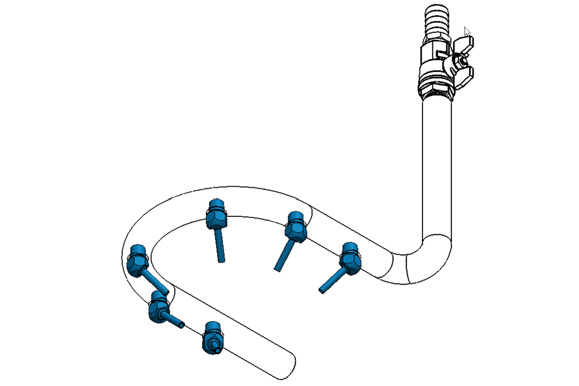
Identify the four swiveling coolant nozzles (PN 38348) and the coolant ring that are included in the kit. Install each nozzle into the coolant ring with a 17 mm wrench. Tighten the nozzles until they're pointed toward the center of the ring.
-
Identify the two coolant ring mounts (PN 51249) included in this kit. Place one coolant ring mount on the right side of the coolant ring (the side opposite of the barbed fitting), and loosely install the coolant ring mount on the right side of the spindle with a 4 mm hex wrench.
-
Slide the remaining coolant ring mount under the left side of the coolant ring. Then, tighten both screws with a 4 mm hex wrench.
-
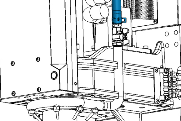
Identify the 12 ft, 1 in. OD hose (PN 51608) and two hose clamps (PN 51558) included with this kit. Install one end of the hose to the barbed hose fitting on the top of the coolant manifold block with one hose clamp and a pair of pliers.
-
Route the loose end of the hose toward the top of the electrical cabinet. Starting at the electrical cabinet, feed the hose through the energy chain toward the back side of the spindle head cover.
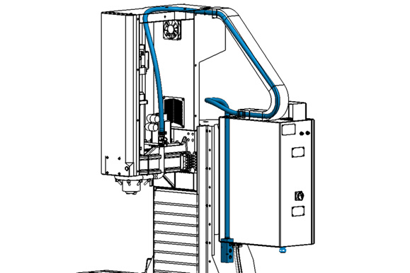
Tip! It may be helpful to have the Z-axis raised to its maximum height, and you may need to remove several of the energy chain covers with a flat-blade screwdriver (or similar) to help route the hose through the energy chain.
-
Route the hose through the opening at the top left side of the spindle head cover.
-
Connect the hose to the barbed fitting on the coolant ring using a pair of pliers and a hose clamp (PN 51558). Make sure the hose clamp is facing toward the front of the machine. If it's not, it may cause interference when you reinstall the side panel.
-
On the side of the coolant ring, turn the handle for the valve to the vertical position. This allows the handle to slip through the hole in the right side spindle cover.
-
Pull the slack from the coolant tube out at the back of the machine.
-
On the right side spindle cover, remove the knock-out hole with a hammer and punch.
-
Reinstall the right side spindle cover panel with a 4 mm hex wrench and the screws that you set aside earlier. It may help to loosen the three bottom screws even further when you're reinstalling the panel.
Install the Manual Sprayer
-
On the top right panel of the enclosure, identify the hole for the washdown bulkhead fitting. Remove the plastic grommet.
-
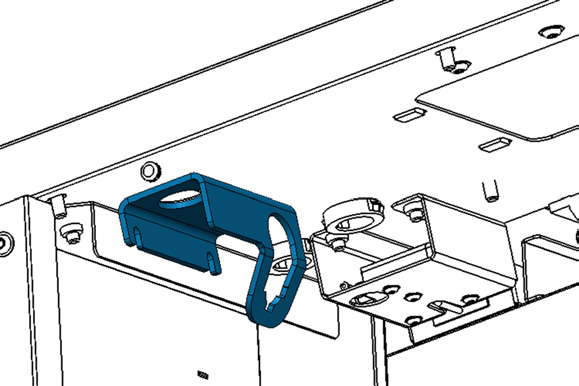
Identify the hose nozzle bracket (PN 51621) and one M6 × 1 - 12 flanged button head cap screw (PN 38206) included in this kit. Mount the bracket to the underside of the top right enclosure panel with a 4 mm hex wrench. Make sure to align the large hole in the bracket with the hole in the top right enclosure panel.
-
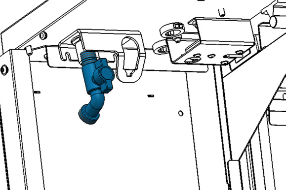
Identify the bulkhead fitting included in this kit. Remove the locking nut from the bulkhead fitting, and install the fitting into the hole in the top of the enclosure panel with the elbow fitting on top of the enclosure. Turn the elbow fitting so that it's pointing at a 45 degree angle toward the spindle and the back of the machine. Then, re-install and tighten the locking nut onto the bulkhead fitting with a 30 mm wrench.
NOTE: You can use a 1-1/8 in. socket wrench as a replacement for a 30 mm wrench.
-
Identify the hose bibb fitting included in this kit. Apply thread sealant tape to its threads. Then, tighten the hose bibb into the bulkhead fitting with a 32 mm wrench on top of the enclosure and an 8 mm hex wrench inserted into the end of the hose bibb. Tighten until the outlet of the hose bibb is pointing toward the front of the enclosure.
-
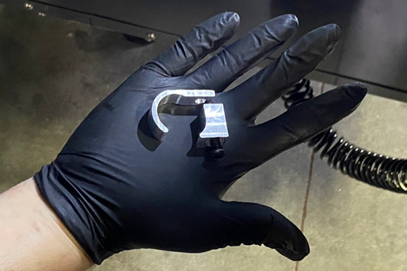
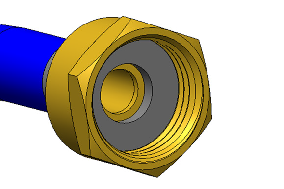
Identify the hose and manual sprayer assembly that's included in this kit. Verify that the rubber seal is installed in the fitting on the loose end of the hose.
-
Connect the hose to the outlet of the hose bibb, and hang the manual sprayer in the loop of the bracket.
-
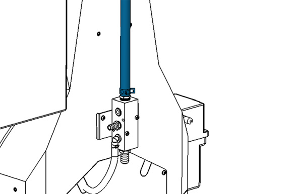
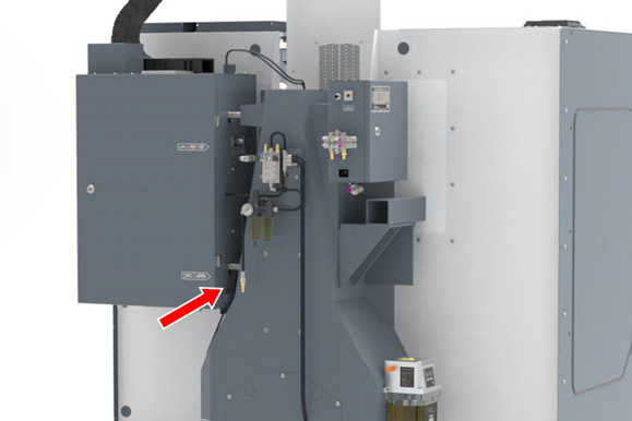
Identify the 7 ft, 5/8 in. OD hose (PN 51516) included in this kit. Connect one end to the straight 1/2 in. barbed hose fitting on the side of the coolant manifold at the back of the machine with a pair of pliers and a hose clamp.
-
Route the loose end of the hose as follows:
-
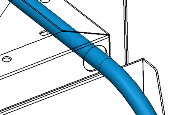
From the coolant manifold, route hose in between the electrical cabinet and the column casting and then back toward the enclosure.
-
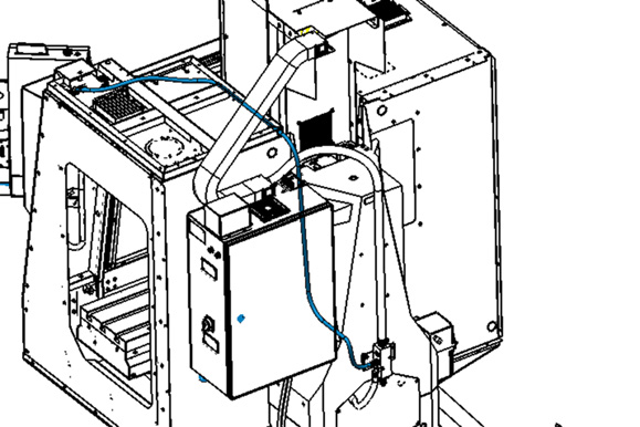
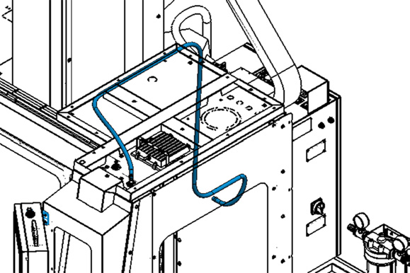
b. Then, route it up toward the top of the enclosure, and through the hole near the spindle head (on the back of the top right enclosure panel).
c. Finally, route the hose through the gap along the edge of the panel.
-
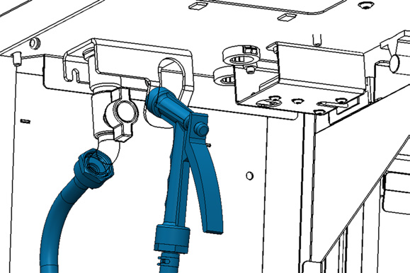
Connect the loose end of the hose to the elbow fitting using a pair of pliers and a hose clamp.
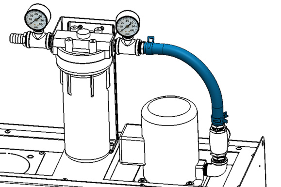
Make Coolant Connections
-
Roll the coolant tank behind the machine and push it up to the back of the machine against the base casting. Center the tank behind the machine, making sure that the chip chutes dump into the chip baskets.
-
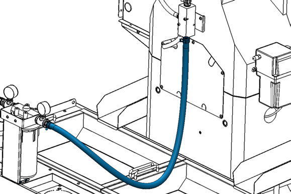
Identify the 4 ft, 1 in. OD hose (PN 51608) included with this kit. Connect one end to the barbed fitting on the outlet of the coolant filter with a pair of pliers and one hose clamp (PN 51558).
-
Connect the loose end of the hose to the barbed fitting on the bottom of the coolant manifold with a pair of pliers and one hose clamp (PN 51558).
-
Plug the flood coolant pump's power cable into the Flood Coolant Power outlet on the side of the electrical cabinet (on the side that's closest to the column).
-
After setting up the flood coolant kit, test the enclosure for coolant leaks. Identify and seal any areas requiring extra sealant.
Looking for more information?
This is a section of the 1500MX operator's manual. To view the whole manual, go to Tormach document UM10811.
If you have additional questions, we can help. Create a support ticket with Tormach Technical Support at tormach.com/how-to-submit-a-support-ticket for guidance on how to proceed.