Background
The idea of providing power to your machine seems simple: just plug it in. In reality, there are a number of other components used in order to provide power appropriately safety for you and the machine, including (but not limited to):
-
The main disconnect switch
-
Fuses and/or circuit breakers
-
Emergency stop switch/button
-
Separate latching circuits for the spindle and rest of the machine
-
Transformers, which change the electricity to the appropriate value
Even with all of these components, you can systematically locate nearly any problem with just a multimeter.
Tools
-
Digital multimeter
Reseat the NEMA L6-30 Plug Into an Outlet
Reason: The machine plug isn’t plugged in to an outlet.
-
Verify that the main power plug is plugged into a known working outlet.
-
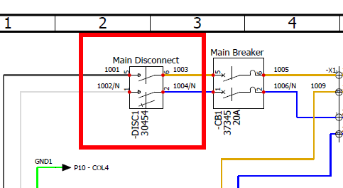
If needed, measure for 208-240 Vac between wires 1001 and 1002/N at the DISC1 Main Disconnect.
Reset Facility’s Breaker for Machine Circuit
Reason: The facility’s mains breaker is tripped.
-
Examine power cable for damage or exposed wires, and then reset your facility’s circuit breaker serving the machine.
-
If needed, measure for 208-240 Vac between wires 1001 and 1002/N at the DISC1 Main Disconnect. (See images above)
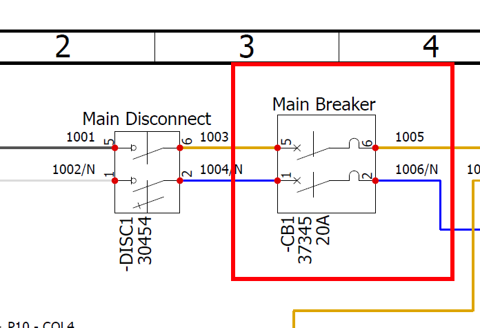
Reset the CB1 Circuit Breaker In the Machine
Reason: The CB1 breaker is tripped.
-
If the mill, controller, accessories, and enclosure lights don’t have power, examine the power cords and wires for damaged or exposed wires, and then reset the CB1 circuit breaker.
-
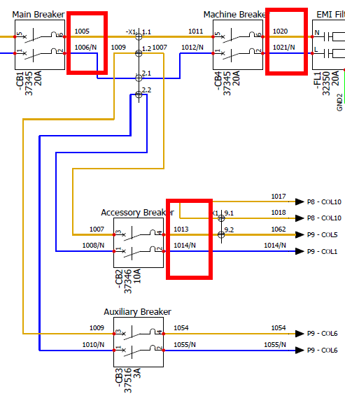
If needed, measure for 208-240 Vac between wires 1005 and 1006/N at the CB1 circuit breaker.
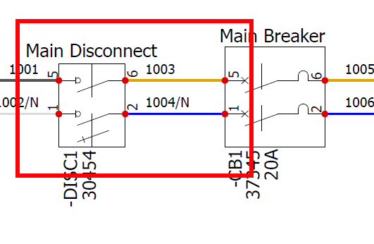
Check the Position of the Main Disconnect Switch
Reason: The Main Disconnect switch is in the OFF position.
-
Switch DISC1 Main Disconnect to the ON position.
-
If needed, measure for 208-240 Vac between wires 1003 and 1004/N at the DISC1 Main Disconnect.
Verify the Machine is Out of Emergency Stop Condition
Reason: The Emergency Stop is pushed in.
-
Twist out the Emergency Stop button and press the Reset button.
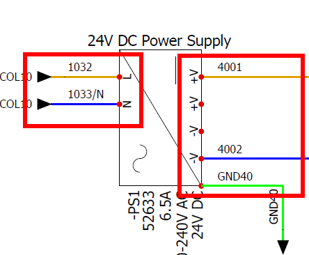
Check the DC Power Supply
Reason: The DC power supply is defective.
-
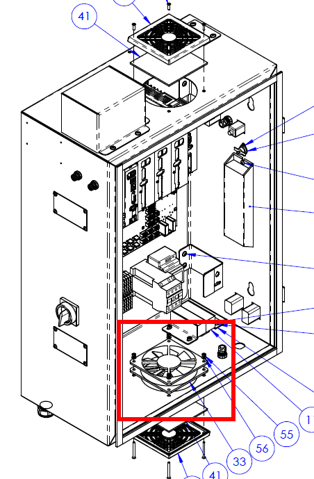
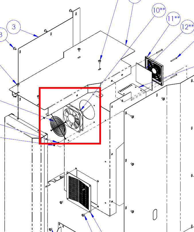
Check if Electrical Cabinet Fan (FAN1) and Spindle Motor Fan (FAN2) are running.
-
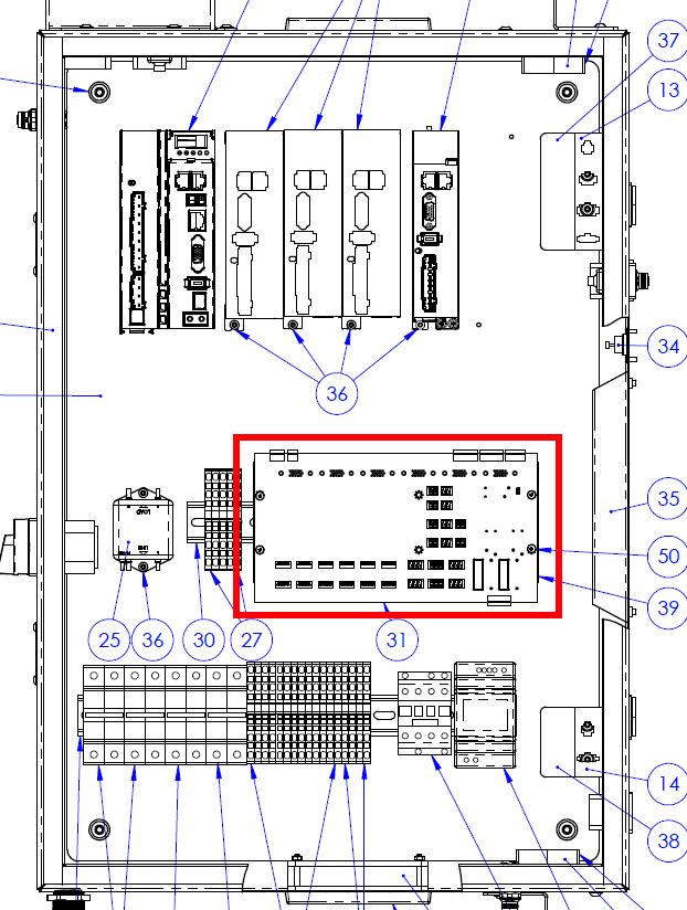
Check for DC OK LED on the PS1 DC power supply.
-
Check for Control Power (D37) LED on E1 Servo IO Breakout Board.
-
Measure for 208 Vac-240 Vac between wires 1032 and 1033/N at the PS1
DC power supply. -
Measure for 24 Vdc nominal between wires 4001 and 4002 at the PS1 DC
power supply.
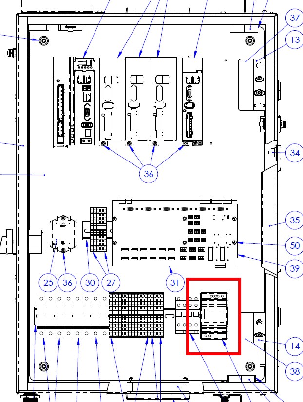
Adjust the DC Power Supply PS1 Output Voltage
Reason: The DC power supply PS1 output voltage is too low.
-
Check if Electrical Cabinet Fan (FAN1) and Spindle Motor Fan (FAN2) are running. (See images above)
-
Check for DC OK LED on PS1 DC power supply. (See images above)
-
Measure for 208-240 Vac between wires 1032 and 1033/N at the PS1 DC power supply. (See images above)
-
Measure for 24 Vdc nominal between wires 4001 and 4002 at the PS1 DC power supply. (See images above)
-
If output voltage is less than 24 Vdc, adjust the output voltage using the +V ADJ trim potentiometer on the front of the PS1 DC power supply.
Reset Machine Circuit Breakers
Reason: The CB1, CB2, or CB4 circuit breaker tripped.
-
Examine the power cords and wires for damaged or exposed wires, and then reset the circuit breaker.
-
If needed, measure for 208-240 Vac between wires 1005 and 1006/N at the CB1 circuit breaker, between wires 1013 and 1014/N at the CB2 circuit breaker, and between wires 1020 and 1021/N at the CB4 circuit breaker.