Before you begin machining operations, you must setup and align the machine. Complete the following steps in the order listed:
Level the Machine
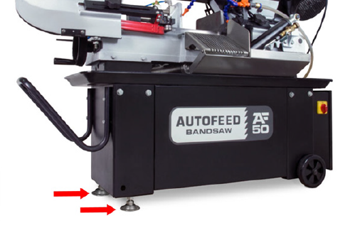
Before operating the machine, you must verify that it's approximately level. While this helps with things like coolant flow, it doesn't impact machine performance.
To level the machine:
-
Make note of any high or low spots, and, if required, adjust the leveling feet.
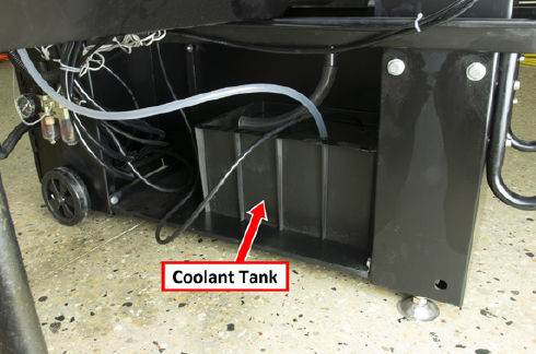
Install the Coolant Tank
-
Find the coolant tank inside the machine's stand.
-
Remove all parts from inside the coolant tank:
-
Coolant screen
-
Coolant tube
-
Roller
-
-
Set aside the roller for later installation.
-
Put the coolant screen on the machine's base below the saw, as shown in the following image.
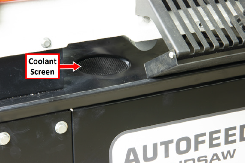
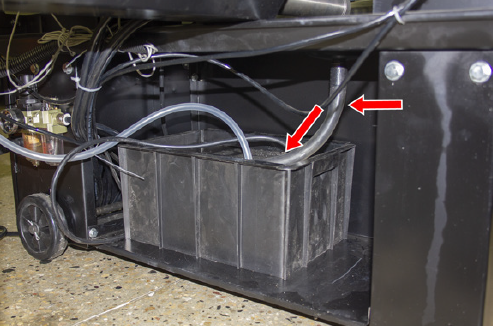
-
Connect the coolant tube to the port below the machine's base, and then put it on top of the tray on the coolant tank, as shown in the following image.
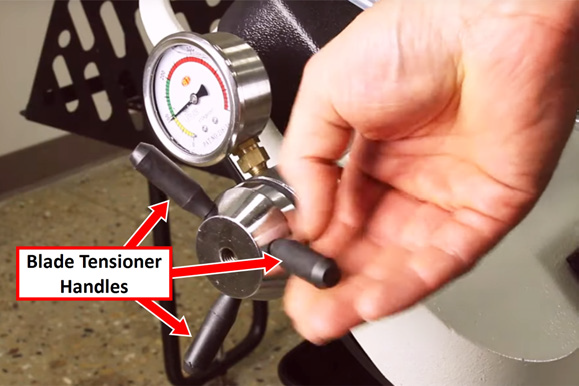
Install the Blade Tensioner Handles
-
Install and hand-tighten the three blade tensioner handles.
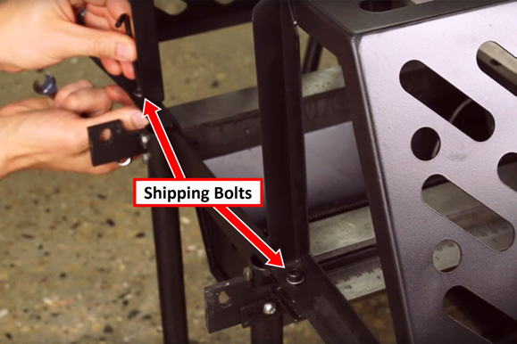
Remove the Shipping Bolts on the Rear Cage
-
The rear cage is secured to the frame for shipment. Remove the two bolts.
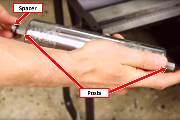
Install the Rear Roller
-
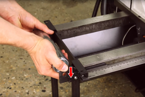
Install the two spacers on either end of the roller posts.
-
Put one roller post into the frame, and then squeeze in the spring-loaded post and slide it into the opposite end of the frame.
Verify Motor Belt Tension
To properly validate the installation of your machine, you must verify that the motor belt is properly tensioned.
To verify the motor belt tension:
-
Verify that the air supply and the machine's main power cable aren't yet connected to the machine.
-
Open the pulley cover.
-
Firmly push the belt between the pulleys. If it's properly tensioned, the belt should move approximately 1/2 in. If it's not properly tensioned, complete the steps in “Change the Speed”.
-
Close the pulley cover.
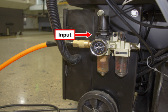
Make Air Connections
-
Connect the air line from your site to the input port on the FRL Filter-Regulator-Lubricator (on the back of the machine).
Air Requirements
-
Air Pressure 90-120 psi (620-825 kPa)
If the air supply is more than 120 psi (825 kPa), you must use a regulator. -
Dry Air We recommend using a compressed air dryer, desiccator, or filter between the air compressor and the machine.
-
Lubricated Air You must lubricate the air with air tool oil.
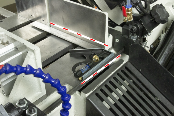
Verify the Alignment of the Fixed Jaw
-
Open the jaws so that there's enough space to put a square in between them.
-
Put a square on the base casting between the jaws.
-
Push the square until it's flush with the side of the blade.
NOTE: The square must be flush with the side of the blade, not the blade's teeth.
-
Confirm that the bottom of the square is flush with the side of the blade, as shown in the following image. If it's not, go to “Align the Fixed Jaw”.
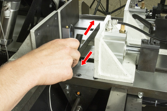
Verify the Alignment of the Infeed Table
-
Move the infeed table so that it meets the base casting.
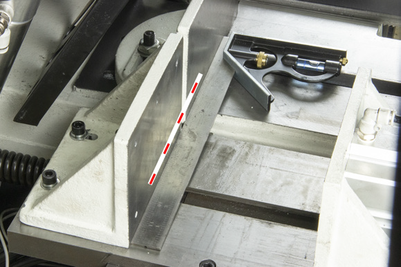
-
Put a square on the base casting as shown in the following image.
-
Keeping the square flat on the base casting, move it back over the infeed table. Make note of any height inconsistencies. If there are height inconsistencies, go to “Adjust the Height of the Infeed Table”.
-
Put a square along the fixed jaws, as shown in the following image. Verify that the square is flush against both jaws. If it's not, go to “Adjust the Fixed Clamp Jaw”.
Looking for more information?
This is a section of the AF50 Autofeed Bandsaw operator's manual. To view the whole manual, go to Tormach document UM10538.
If you have additional questions, we can help. Create a support ticket with Tormach Technical Support at tormach.com/how-to-submit-a-support-ticket for guidance on how to proceed.