In This Section, You'll Learn:
About adjustments that may be required to operate your machine as expected.
Before operating the machine in any way, you must read and understand this section.
Adjust the Blade Guides
-
Power off the bandsaw and disconnect it from the main air supply.
-
Push the Emergency Stop button on the operator panel to lock it into the disabled position.
-
Turn the Main Disconnect switch to OFF.
Mains power is disconnected from the machine. -
Disconnect the air line from your site from the input port on the FRL Filter-Regulator-Lubricator.
-
-
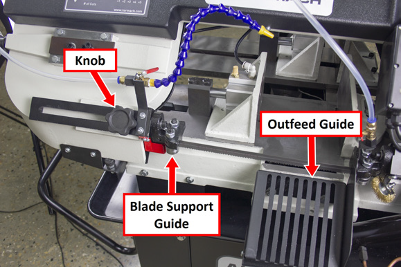
Identify the knob on the blade support guide. Then, loosen it.
-
Move the blade support guide toward the material. Stop when it's close to the material, but not past the outfeed guide.
-
Tighten the knob on the blade support guide.
Adjust the Blade Tracking
WARNING! Crush Hazard: Moving parts can entangle, pinch, or cut you, causing death or serious injury. While operating the machine in vertical position, you must keep your hands away from the blade.
-
Put on work gloves, eye protection, and any other appropriate personal protective equipment. We recommend a long-sleeved shirt and long pants.
-
Power off the bandsaw and disconnect it from the main air supply.
-
Push the Emergency Stop button on the operator panel to lock it into the disabled position.
-
Turn the Main Disconnect switch to OFF.
Mains power is disconnected from the machine. -
Disconnect the air line from your site from the input port on the FRL Filter-Regulator-Lubricator.
-
-
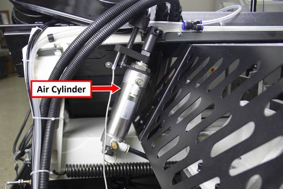
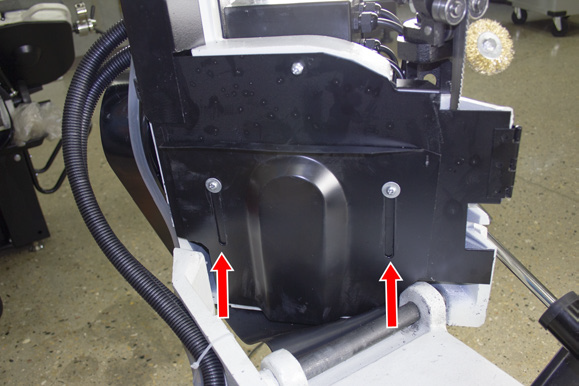
On the back of the machine, identify the air cylinder, as shown in the following image.
-
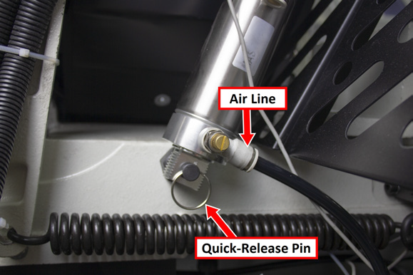
Turn the air line valve, which allows you to access the air cylinder's quick-release pin, as shown in the following image.
-
Pull the quick-release pin out of the air cylinder, and set it aside.
The air cylinder hangs from the saw head. -
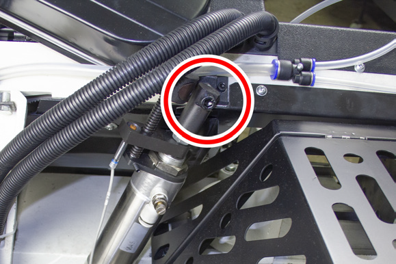
Remove the bolt securing the air cylinder to the bandsaw with an 8 mm hex wrench.
-
Set aside the bolt and the air cylinder.
-
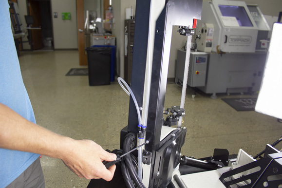
Lift the saw head to the upright position, as shown in the following image.
-
Loosen the two screws on the bottom of the blade cover with a Phillips screwdriver, and then slide the blade cover up until it clears the base casting.
-
Remove the two screws from the side of the blade cover, and then set aside the screws.
-
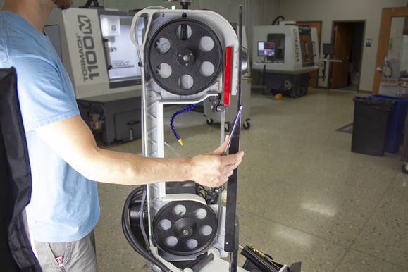
Open the blade cover, as shown in the following image.
-
Identify the tensioner on the top of the saw head.
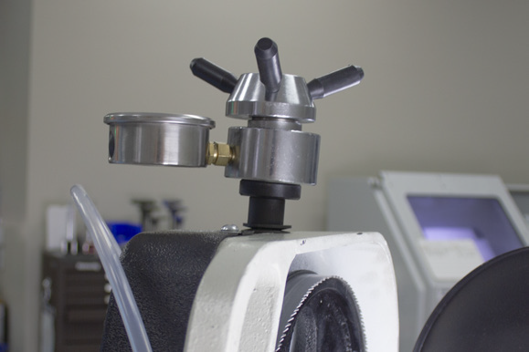
-
Verify that the blade tension is set correctly.
-
Power on the bandsaw.
-
Rotate the Emergency Stop button on the operator panel one-quarter turn clockwise to release it.
-
Turn the Main Disconnect switch to ON.
Mains power is connected to the machine.
-
-
Set the bandsaw to manual mode: from the control panel, push the Down Arrow and Up Arrow buttons at the same time. The control board displays ---.
WARNING! Crush Hazard: Moving parts can entangle, pinch, or cut you, causing death or serious injury. While operating the machine in vertical position, you must keep your hands away from the blade.
-
From the operator panel, push the Cycle Start button.
The blade moves through the blade guides and around the blade wheels. -
Observe the blade as it moves:
-
Correct Tracking The blade runs next to, but not directly against, the wheel shoulder.
-
Incorrect Tracking Go to Step 16.
NOTICE! You must not let the blade run directly against the wheel shoulder. If you do, it could cause damage to the bandsaw or the blade.
-
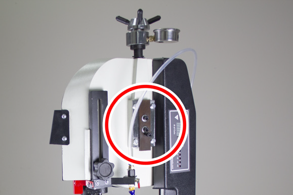
Identify the two socket head cap screws with washers on the front of the bandsaw. Then, loosen them with a 6 mm hex key wrench.
-
Identify the socket head cap screw without a washer.
-
Use the socket head cap screw without a washer to adjust the blade tracking. While observing the blade as it moves, do one of the following:
-
Track Closer to Wheel Shoulder Turn the socket head cap screw without a washer clockwise.
-
Track Away from Wheel Shoulder Turn the socket head cap screw without a washer counterclockwise.
-
Put a piece of paper between the blade and the wheel to test the blade tracking.
-
With the paper held in place, slowly turn the socket head cap screw without a washer to track the wheel closer to the shoulder. Continue turning until the paper is cut into two pieces.
-
Slowly back off the socket head cap screw without a washer to move it slightly away from the wheel shoulder.
-
Tighten the two socket head cap screws with washers on the front of the bandsaw.
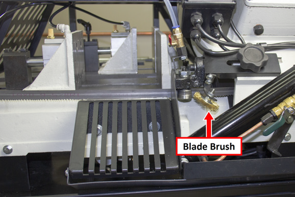
Adjust the Blade Brush
NOTICE! You must verify that the blade brush is adjusted correctly and regularly maintained. If you don't, it could cause damage to the blade. For information, see Machine Maintenance.
To adjust the blade brush:
-
Identify the blade brush.
-
Adjust the blade brush until its bristles overlap the blade.
If the Blade Brush (PN 38033) is worn or damaged, you must replace it.
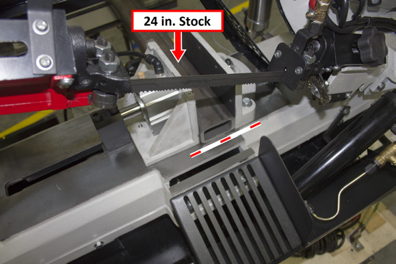
Adjust the Height of the Infeed Table
-
Find a piece of 24 in. stock. We recommend using one of the following:
-
Cold-rolled steel (that's at least 1 in. square)
-
Extruded aluminum (that's at least 1-1/2 in. square)
-
Structural tubing (that's at least 1-1/2 in. square)
-
Move the infeed table so that it's approximately in the center of travel.
-
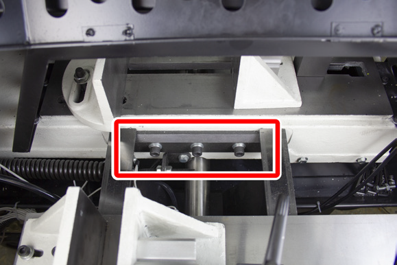
Loosen three M10 socket head cap screws on the base casting. This allows you to adjust the height of the infeed table.
-
Open the clamps on both vises with the handwheel and the clamp handle. Then, load the stock between the vises as shown in the following image.
-
Close the vise with the handwheel until the material is secure. Verify that the stock is flat against the entire length of the base casting.
-
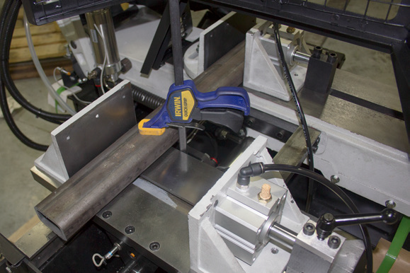
Lift and secure the guide rail and the infeed table to the stock with clamps, as shown in the following image.
-
Tighten the three M10 socket head cap screws that you loosened in Step 3.
-
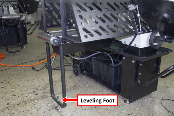
If required, adjust the leveling foot.
-
Remove the clamps from the machine.
-
Remove the stock from the machine.
Adjust the Jaws
Complete the following steps in the order listed:
Align the Fixed Jaw
-
Open the jaws so that there's enough space to put a square in between them.
-
Put a square on the base casting between the jaws.
-
Push the square until it's flush with the side of the blade.
NOTE: The square must be flush with the side of the blade, not the blade's teeth.
-
Loosen the two screws securing the fixed jaw to the base casting with a box end wrench.
-
Tap the fixed jaw until it's flush with the side of the square. Verify that the square is still flush with the side of the blade.

-
Tighten the two screws securing the fixed jaw to the base casting. Confirm that it remains flush with the square.
-
Remove the square from the base casting.
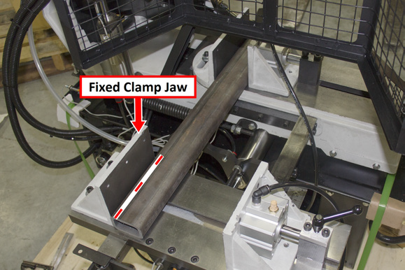
Adjust the Fixed Clamp Jaw
-
Find a piece of 24 in. stock. We recommend using one of the following:
-
Cold-rolled steel (that's at least 1 in. square)
-
Extruded aluminum (that's at least 1-1/2 in. square)
-
Structural tubing (that's at least 1-1/2 in. square)
-
Open the clamps on both vises with the handwheel and the clamp handle. Then, load the stock between the vises as shown in the following image.

-
Close the vise with the handwheel until the material is secure. Verify that the stock is flat against the entire length of the base casting.
-
Loosen the four M8 socket head cap screws securing the fixed clamp jaw to the infeed table.
-
Secure the stock to the fixed jaw with a clamp.
-
Tap the fixed clamp jaw until it is flush with the side of the stock.
-
Tighten the four M8 socket head cap screws that you loosened in Step 4. Verify that the fixed clamp jaw remains flush with the stock.
-
Remove the clamp from the machine.
-
Remove the stock from the machine.
Looking for more information?
This is a section of the AF50 Autofeed Bandsaw operator's manual. To view the whole manual, go to Tormach document UM10538.
If you have additional questions, we can help. Create a support ticket with Tormach Technical Support at tormach.com/how-to-submit-a-support-ticket for guidance on how to proceed.