Background
In the event your Z-axis limit switch harness needs to be replaced, due to a damaged or non functional limit switch or physical touch switch, the instructions below will walk you through the process.
Tools
-
Metric Allen Key Set
-
Small Phillips Screwdriver
-
Crimper
-
Wire Snips
-
PN 51804-P
Remove Power from the Machine
Make sure to remove power from your machine before starting on any part removal.
Disassembly and Removal of Harness
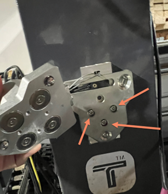
Remove the Torch Mount
Remove the magnetic torch holder. Proceed to then remove the three indicated mounting bolts. You can also remove the tool crash detection sensor as well, if needed.
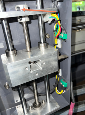
Loosen the Lead Screw Coupler
Once the face plate is removed, loosen the top most coupler screw, indicated below.
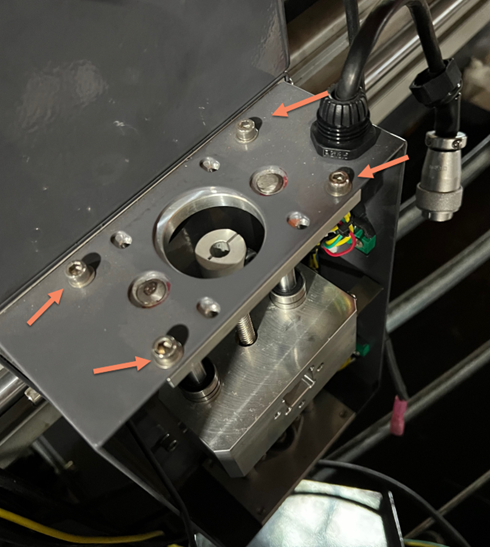
Remove the Motor from the top of the Z-Axis Assembly
Remove the motor power plug from the quick connect junction. Then remove the four motor mounting screws.
.png?cb=7401027151ce36b69f42c1f3caf7999a)
.png?cb=15728ce01c835d97e9e687b65ded63b4)
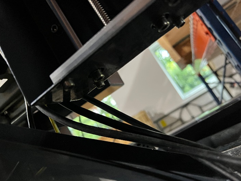
Remove the Lead Screw Assembly
With the motor removed, the lead screw assembly is free to be removed. There are four mounting bolts on both the top and bottom side of the panel assembly.
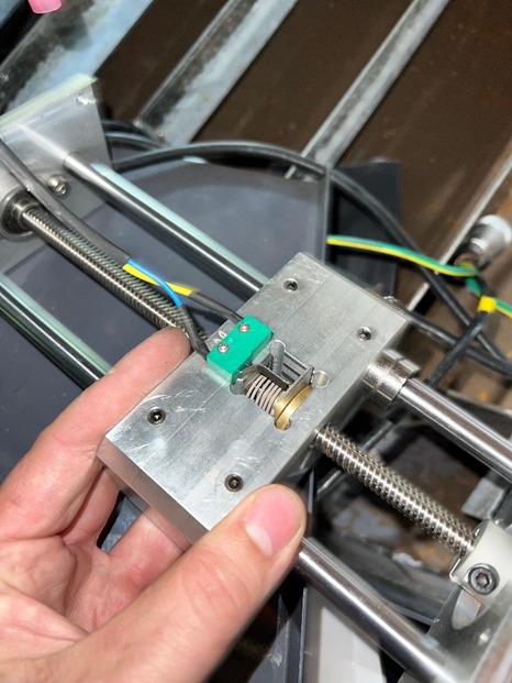
Remove the Physical Touch Switch
When removing the lead screw assembly, you will find the physical touch switch mounted with screws, on the back of the assembly itself.
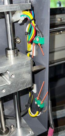
Remove the Upper and Lower Limit Switches
The upper and lower limit switches are both mounted with two screws. Remove the screws, and snip any zip ties.
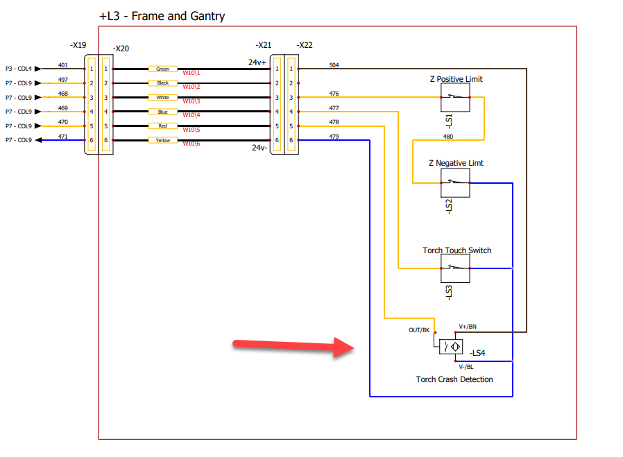
Disconnect the Torch Crash Detection Molex Plug
When you disconnect the plug seen below, take note of which pin goes to which. When the new harness is installed, you will be clipping off this connector, and splicing in the new connector.
.png?cb=d583c3845cef85a4061dfb6b79d87c6f)
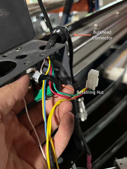
Remove the Original Harness
Remove the harness power, and unscrew the bulkhead retainer on the top of the panel. Plumb the harness through the access hole. This part is a bit cumbersome, as the switches need to be carefully passed through the retaining nut, before being able to be pulled through the top of the panel. Some of the connection paints on the limit switches will be bent. This is ok, as long as the solder connection is not broken off. If you would like to be extra safe, skip putting the provided retaining nut back on the harness. The downside of this, that the bulkhead will not be tight, but this will not affect machine performance.
Installation of Replacement Harness
Physical Touch Switch
When installing the physical touch switch, you will need to manually bend the flag of the switch up, so that it is able to be tripped by the spring loaded flag. Make sure to reset the physical touch off distance in PathPilot after the install. The procedure can he found here: Basic Operations - 1300PL | Touch Switch Trigger Depth
Crash Detection Sensor
Cut off the molex connection, if present, on your existing sensor. Using the supplied butt splices, crimp together the new harness to the crash detection sensor.
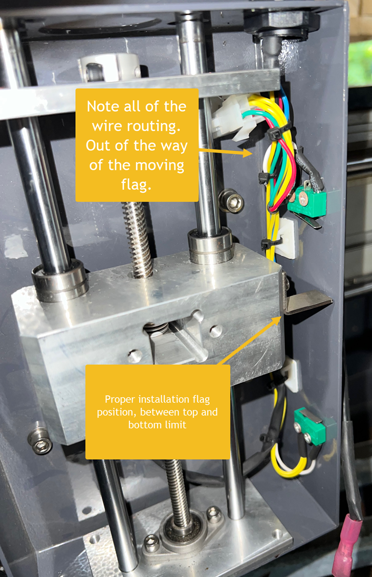
Mounting the Harness
The most important detail to watch for, is the position of the flag on the lead screw assembly that trips the upper and lower limit switches. When you reinstall the assembly, ensure that the trip flag is properly positioned between both limit switches. Be aware of your wire routing, so that the harness isn’t tugged on, when motion is commanded.
Follow the disassembly instructions in reverse to complete the install.
If you run into any issues, reach out to Tormach Technical Support.