In This Section, You'll Learn:
How to use PathPilot, depending on the activity that you want to do.
Create and Load G-Code Files
To get started with PathPilot, you must first load or create a G-code file.
Load G-Code
To run a G-code program on a PathPilot controller, you must first verify that the file is on the controller. For more information on transferring and moving files, see "Transfer Files to and From the Controller".
To load G-code:
-
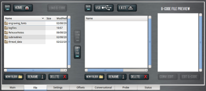
From the File tab, in the Controller Files window, select the desired .nc file.
-
Select Load G-Code.
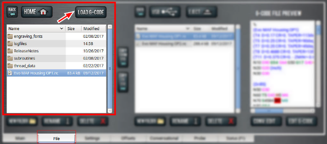
NOTE: This function is only available for files stored on the PathPilot controller.
PathPilot loads the G-code file and opens the Main tab.
Transfer Files to and From the Controller
To run a G-code program, you must transfer the files to the PathPilot controller. You can either use a USB drive or PathPilot HUB (our cloud-based simulator) to transfer files. For more information on PathPilot HUB, go to hub.pathpilot.com.
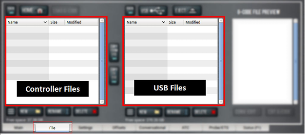
To transfer files to and from the controller:
-
Either insert a USB drive into any open USB port, or sign in to PathPilot HUB.
-
From the File tab, select the file to transfer (either in the USB / HUB Files window or the Controller Files window).
NOTE: Select Back to move backward and either Home or USB to move to the highest level.
-
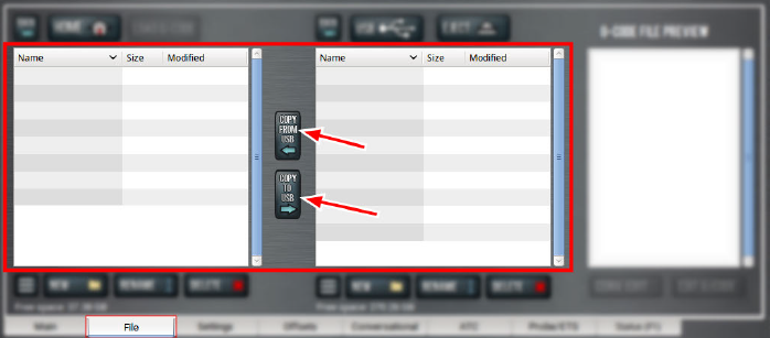
Select the location to which you want to copy the transferred file.
-
Select either Copy ← or Copy →.
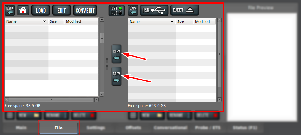
NOTE: The file must have a unique name. If it doesn't, you must either overwrite the file, rename the file, or cancel the file transfer.
-
If you're using a USB drive, select Eject.
It's safe to remove the USB drive from the controller.
Preview G-Code Files
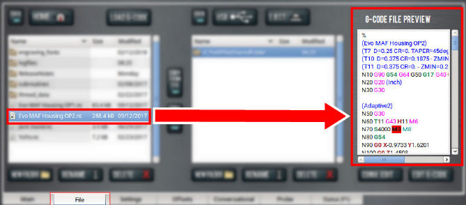
You can preview an .nc file that's either on the PathPilot controller or on a USB drive.
To preview G-code files:
-
From the File tab, in the Controller Files window or the USB Files window, select an .nc file.
The text displays in the Preview window.
Access Recent G-Code Files
You can load a recently loaded G-code file from the Main tab. For information, see "About the G-Code Tab".
To access recent G-code files:
-
From the Main tab, in the G-Code tab, select the Recent Files menu.
The last five program files loaded into PathPilot display.
-
Select the name of the desired G-code program.
The G-code program loads.
Close the Current Program
-
From the Main tab, on the G-Code tab, select the Recent Files menu.
-
Select Clear Current Program.
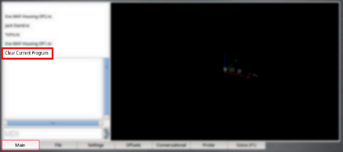
The currently loaded G-code program closes.
Edit G-Code with a Text Editor
You can edit .nc files that are on the PathPilot controller. If the .nc file is in the USB Files window, you must first transfer it to the controller; go to "Transfer Files to and From the Controller".
To edit G-code with a text editor:
-
From the Controller Files window, highlight the .nc file and select Edit G-code.
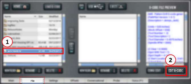
The file opens in a text editor.
-
Make and save the appropriate changes to the file.
-
Close the text editor.
Tip! To quickly edit an already loaded G-code program from the Main tab, you can use a keyboard shortcut: Shift+Alt+E.
Read G-Code
Once your G-code file is loaded into PathPilot, you can read it in the following ways:
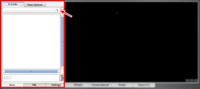
Expand the G-Code Tab
You can change the size of the G-Code tab if you need more space to view the code. For more information on using the G-Code tab, see "About the G-Code Tab".
To expand the G-Code tab:
-
Select the Window Expander.
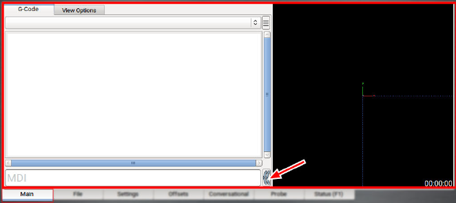
The Tool Path display shrinks.
About the G-Code Tab
The G-Code tab displays the code of the currently loaded program file. Use the scroll bars to view the entire file. You can make the G-Code tab larger. For information, see "Expand the G-Code Tab".
PathPilot highlights certain lines of code of interest. When running a G-code program in single block mode, there may be as many as two lines of G-code highlighted, both with a different color:
-
Green Line Indicates the start line (the line from which PathPilot starts the program).
To change the start line, go to "Set a New Start Line". -
Orange Line Indicates the line of code that PathPilot is currently executing.
Search in the Code
You can use PathPilot to search the text of a G-code program file for specific numbers, codes, or other items of interest (like tools, feeds, and speeds).
To search in the code:
-
From Main tab, on the G-Code tab, select any line of code to use as a starting point.
-
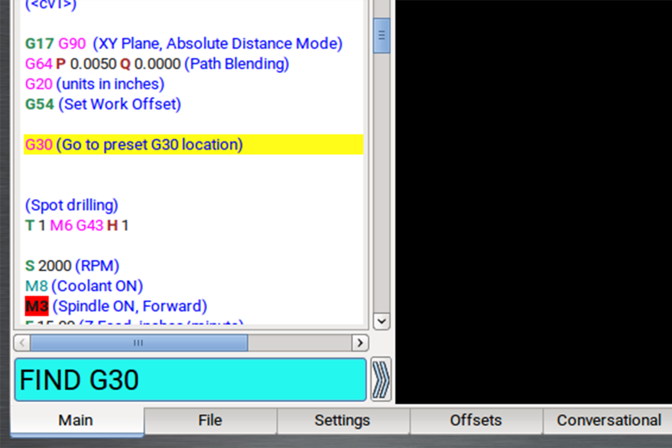
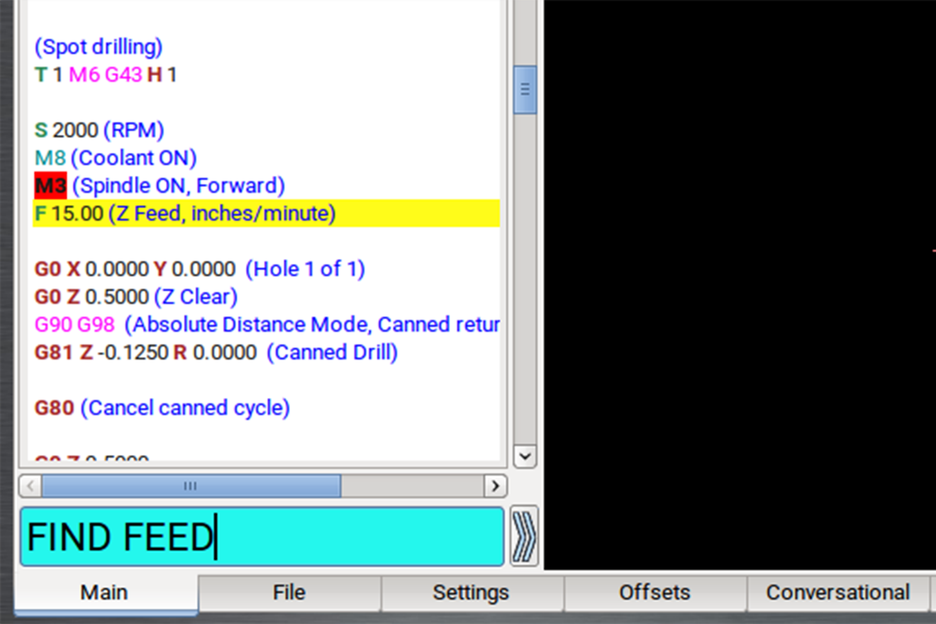
In the MDI Line DRO field, type Find followed by one of the following:
-
Any text. PathPilot searches for instances of the specific number or code.
-
Feed. PathPilot searches for instances of the actual word Feed and any F G-code command.
-
Speed. PathPilot searches for instances of the actual word Speed and any S G-code command.
-
Tool. PathPilot searches for instances of the word Tool and any T G-code command.
NOTE: The find command is not case-sensitive.
-
Select the Enter key.
If PathPilot finds the information, the searched term is scrolled to and highlighted in the G-Code tab. -
(Optional) Select Enter.
PathPilot finds the next instance of the searched text. -
(Optional) Select Enter+Shift.
PathPilot finds the previous instance of the searched text.
NOTE: When the search reaches the end of the G-code file, it starts again from the beginning.
Set a New Start Line
The start line (the line from which PathPilot starts the program) is, by default, the first line of code in the program.
To set a new start line:
-
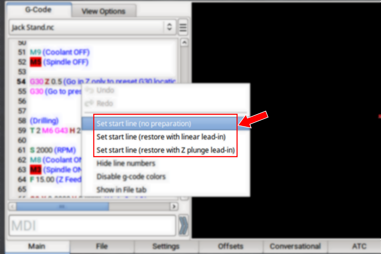
From the Main tab, on the G-Code tab, do one of the following:
-
Right-click any line in the program.
-
Tap the line. Then, select the Options menu.
-
Select the desired lead-in move. For information, see "Lead-In Moves".
Lead-In Moves
-
Set start line (no preparation) Keep the current tool in the spindle, with the current tool length applied. The machine executes the start line from the current position.
NOTE: We don't recommend this option for starting partway through a cut.
Example
-
Starting the program at a tool change.
-
Starting the program with a different tool in the spindle than the program calls for (like if your tool broke, which you've replaced, but you'd rather not edit the entire program or the tool table entry).
-
Set start line (restore with linear lead-in) Perform a tool change (as required). The machine rapids in X and Y, then Z to the current position, then feeds in a straight linear line to the start line position.
NOTE: This option assumes that the current position is the lead-in position.
Example
Quickly resuming work after stopping the program to make an adjustment to the machine setup (like clearing chips, removing an object, or turning on the coolant pump). Because the machine's already set up, you can position the tool near the stopping point.
-
Set start line (restore with Z plunge lead-in) Perform a tool change (as required). The machine rapids in Z to G30 clearance height, rapids in X and Y to the start line position, then feeds in Z to the start line position.
Example
Running a sub-section of a large program when the correct tool isn't loaded (and positioning the tool tip near the starting point is difficult, like with a long tool or fly cutter loaded). This option doesn't require you to jog to the exact lead-in position.
Change the View of the Tool Path Display
-
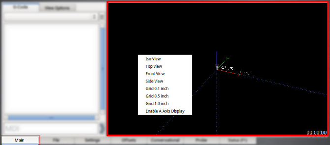
From the Main tab, do one of the following:
-
Right-click the Tool Path display.
-
Select the View Options tab.
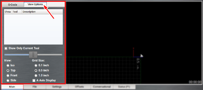
-
Select a new view.
For information, see "About the Tool Path Display".
About the Tool Path Display
The Tool Path display is a graphical representation of the currently loaded G-code file's tool path.
Depending on which programming mode you're in (G20 or G21), PathPilot defaults to one of the following grid line spacings:
-
G20 Mode 1/2 in. intervals
-
G21 Mode 5 mm intervals
In the Tool Path display, there are four different line types:
-
Dotted Blue Lines Indicate the boundary box (the ends of travel of the axes).
-
Red Lines Indicate the tool path as it is cut.
NOTE: The Tool Path display shows the program extents — the furthest points to which the tool will travel while running the program — of the currently loaded G-code file alongside the tool path lines.
-
White Lines Indicate the preview lines.
-
Yellow Lines Indicate the jogging moves.
To erase the jogging moves (yellow line) or the tool path (red lines), do one of the following:
-
Double-click anywhere in the Tool Path display.
-
Select Reset.
Import a DXF File
You can import a .dxf file (Drawing Exchange Format) into PathPilot to generate G-code, which can then cut the shape (or shapes) described in the .dxf file. For example, you could use this feature to engrave logos or artwork.
-
From the Conversational tab, select the DXF tab.
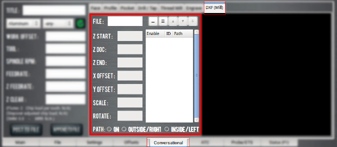
-
Select the File DRO field.
The File Selector dialog box opens. -
Select the .dxf file, and then select Open.
-
The shapes from the selected file are loaded into the Preview window.
NOTE: The .dxf file must already be transferred to the PathPilot controller. For information, see "Transfer Files to and From the Controller".
-
In the X Offset DRO field and the Y Offset DRO field, type the offset value added in the XY direction from the bottom left corner of the .dxf drawing.
-
In the Scale DRO field, type the scale factor for the drawing. The value typed in the Scale DRO field is used as a multiplier for the .dxf dimensions, and is used for the entire drawing.
Example
If you type 1.0 in the Scale DRO field, the .dxf is scaled at 100%.
If you type 2.0 in the Scale DRO field, the .dxf is scaled at 200%.
-
In the Rotate DRO field, type the rotation angle in degrees.
The rotation angle is applied around the Z-axis of the drawing’s origin. -
Select one of the following to set the cutter compensation to be applied to the tool path:
-
On: The tool moves along the path.
-
Outside / Right: Offsets the tool path right of the drawing path, seen from the direction where the tool enters the path.
-
Inside / Left: The opposite of Outside / Right.
Working with Layers and Shapes
The .dxf file contains shapes grouped into layers.
In the Shape Selection tree view window, you can enable or disable individual layers and complete layers. You can select shapes either from the tree view window or in the Preview window.
Change the Layer or Shape Cut Order
-
Use the Up Arrow and Down Arrow buttons above the Shape Selection tree view window.
Shapes or layers higher in the tree view window are cut earlier than those below it. The order in which the shapes are cut is the same as the order of the enabled shapes in the tree view window and the cyan path in the Preview window.
NOTE: If a layer is selected, the whole layer is moved up or down. Shapes can’t be moved between layers.
Adjust the Tree View Window
-
Use the Fold and buttons to collapse and expand the layer and shape tree in the tree view window.
Working in the Preview Window
The Preview window uses the following colors:
-
Cyan Selected paths
-
Gray Disabled paths
-
White Drawing path
-
Magenta Cut path
-
Dark Cyan Stippled Line Tool path between cuts
-
The coordinates use the following colors:
-
Red X-axis
-
Green Y-axis
-
Blue Z-axis
-
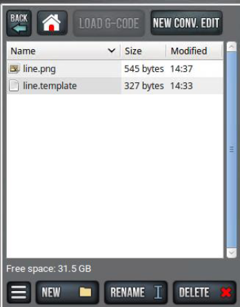
Create and Add Shape Library Templates
Starting with PathPilot v2.9.0, you can create and add new templates to the Shape Library system.
Templates consist of two files:
-
.template: A parametric G-code file that serves as the actual template.
-
.png: A thumbnail image to identify it in the shape library.
Tip! We recommend that you create templates externally in your favorite G-code editor and then copy them to your PathPilot controller like you would any other file.
Create a Template
-
Create a new file named [shape_name].template, where [shape_name] is your desired template name.
Example
To create a template for a welding bracket, make the file name welding_bracket.template.
-
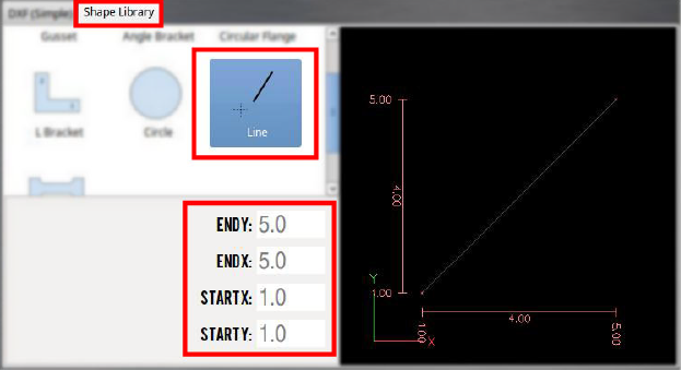
Inside the file that you created in Step 1, you can write regular G-code with the addition of special parametric variables that PathPilot uses to display adjustable parameters in the Shape Library.
The following example is a template file that creates a line from one (X, Y) location to another:
line.templateText#<start_x> = 1.0 (PARAMFLOAT)
#<start_y> = 1.0 (PARAMFLOAT)
#<end_x> = 5.0 (PARAMFLOAT)
#<end_y> = 5.0 (PARAMFLOAT)
G20 (set units to inches)
G91.1 (Restore Incremental Arc Distance Mode)
G90 (Absolute Distance Mode)
G30
M200
G0 X[#<start_x>] Y[#<start_y>]
G15
G16
(Cut to end of line)
G1 X[#<end_x>] Y[#<end_y>]
M205
NOTE: The special lines at the top each create a parameter that PathPilot recognizes and displays on screen. Each parameter can either have the type PARAMFLOAT or PARAMINT for floating point numbers or integers, respectively.
-
(Optional) Once you've written the G-code for your template, you can create a .png image to use as the thumbnail. The image must:
-
Be sized to 256 pixels × 256 pixels.
-
Use a file name that matches the template name.
Example
A thumbnail for the template welding_bracket.template requires an image with the file name welding_bracket.png.
Add a Template
-
From the PathPilot controller, on the File tab, find the plasma_library_templates folder inside the Home directory. If you don't see this folder, make sure that you've updated to the latest version of PathPilot.
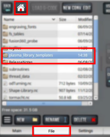
-
Copy the .template file and the .png file that you created into the plasma_library_templates folder.
-
Restart PathPilot.
Your new template displays on the Shape Library tab, with any defined parameters from the .template file displayed as configurable options.
Machine Settings and Accessories
Before running a G-code program, you must first make sure that the machine settings are properly configured.
Enable an Internet Connection
If desired, you can enable an internet connection on your PathPilot controller. An internet connection allows you to receive automatic PathPilot updates and transfer files with PathPilot HUB instead of a USB drive.
To enable an internet connection:
-
From the PathPilot interface, on the Status tab, select Internet.
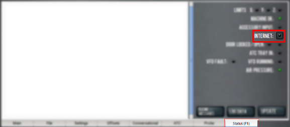
The Network Configuration dialog box displays.
-
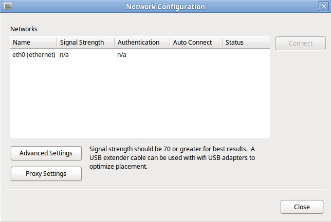
From the Network Configuration dialog box, in the Networks list, select the network you want to use. Then, select Connect.
NOTE: Wi-Fi connection signal strengths are indicated on a scale of 0 to 100, with 100 being the strongest. PathPilot continually refreshes the signal levels to help you find the best placement for your Wi-Fi network adapter. Ethernet connections are indicated by a prefix in the following format: eth[NUMBER]. For example, eth1.
The PathPilot operating system connects to the internet using the network you specified. It continues to detect and connect to the Wi-Fi network, even after power cycles.
Enable Automatic Updates
NOTE: Automatic updates require an internet connection. If you haven't yet enabled it, go to "Enable an Internet Connection".
If desired, you can enable automatic updates for PathPilot.
To enable automatic updates:
-
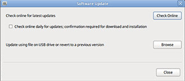
From the PathPilot interface, on the Status tab, select Update.
The Software Update dialog box displays.
-
From the Software Update dialog box, select the Check online daily for updates; confirmation required for download and installation checkbox.
-
Select Close.
When future updates are available, the Status tab displays a notification.
Change the Network Name
If you're connected to a network using either the Ethernet jack or the (optional) Wireless Network Adapter (PN 38207), the PathPilot controller appears on your network as network-attached storage. The default network name of the controller is TORMACHPCNC.
To change the network name:
-
From the Network Name field, type a new network name.
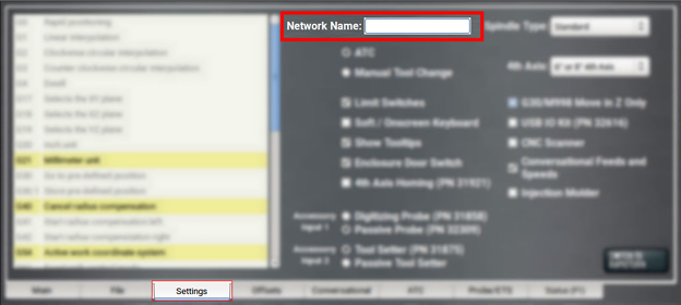
NOTE: The network name must be unique within your network.
-
Select the Enter key.
-
For the change to take effect, you must restart the controller.
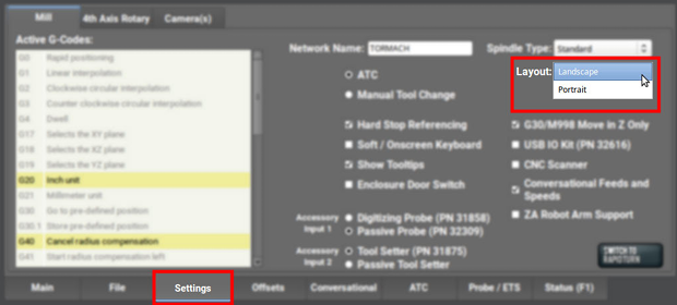
Change the Screen Orientation
A vertical orientation for 1920 × 1080 monitors is supported in PathPilot v2.10.0 and later. For more information on the portrait layout, go to "About Portrait Screen Layout" (page 16).
To change the screen orientation:
-
From the PathPilot interface, on the Settings tab, select Portrait from the Layout drop-down menu. Restart the controller.
-
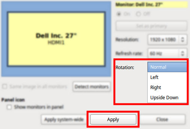
Rotate the monitor to the portrait orientation. You can rotate it either left or right, depending on what's easier for your setup.
-
While the controller is restarting, specify which direction you've rotated the monitor. Select Apply. If the result is unexpected, click Restore Previous Configuration on the confirmation dialog and choose a rotation direction again.
The controller restarts in portrait layout.
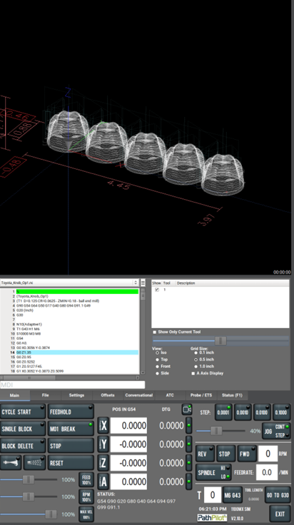
About Portrait Screen Layout
Portrait layout provides some key advantages:
-
A larger tool path window that's always visible at the top of the screen, regardless of which tab you have active.
-
A wider G-code window to more easily read the loaded G-code file and, if enabled, line numbers.
-
The tool path window's view options are always visible for much easier access.
-
When browsing G-code files using the File tab, file previews display on the top portion of the screen.
Set Torch Touch Trigger Depth
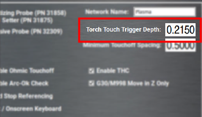
When using the physical touchoff switch for material height sensing, there's a certain amount of lost motion in the Z-axis between when the torch head touches the material and when the micro-switch in the torch lifter triggers.
It's important to set an accurate value for the distance between torch touch and touch switch triggering so that the initial pierce height can be correctly computed.
To set torch touch trigger depth:
-
Power on the machine and reference all axes.
-
From the PathPilot interface, on the Settings tab, disable Ohmic Touchoff.
-
Put a piece of material on the machine table and position the torch above it.
-
Using a slow jog speed (~5 IPM), jog the torch down until it's just contacting the material.
-
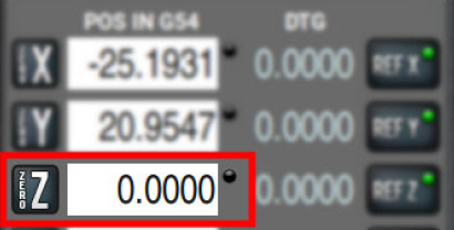
Zero your Z-axis at this position.
-
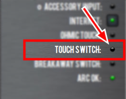
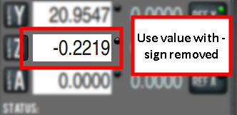
Switch to the Status tab and watch the Touch Switch LED. Very slowly, jog downwards until the LED comes on.
-
Note the value in the Z DRO field. This is your Torch Touch Trigger Depth. Convert this value to a positive number and enter it on the Settings tab.
-
Re-enable Ohmic Touchoff on the Settings page.
Set Minimum Touchoff Spacing
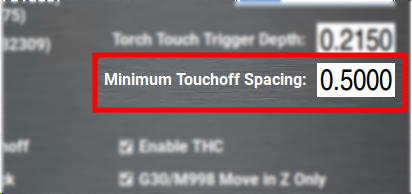
Minimum touchoff spacing is a time saving setting designed to avoid unnecessary probing during programs with a large number of individual cuts.
After the machine has probed for initial cut height, if the next cut begins within this distance it will be assumed that the material height is the same. This allows the machine to skip the probing routine and proceed straight to pierce height.
If your material is very flat and uniform, you can use a large distance for this setting (>2 in.). If your material is uneven or you would simply prefer to probe for height every time a cut begins, enter zero for this value.
Enable Ohmic Touchoff
This setting disables the ohmic sensing system entirely and relies solely on the physical touch switch for height sensing. This can be useful for cutting programs that result in water being repeatedly splashed into the torch nozzle, causing spurious probing trips.
NOTE: Do not disable ohmic touch-off when cutting very thin material. The weight of the torch will bend the material during probing and cause inaccurate pierce height.
Enable Torch Height Control
Disabling this setting stops all dynamic height adjustment during cutting. The torch will stay at the same height for the length of a cut and not adjust to follow the contours of the material.
Enable Arc-Ok Checking
Hypertherm plasma sources supply an arc-ok signal to PathPilot when the cutting arc is fully established. When this setting is enabled, the machine will pause during a G16 pierce until is receives an arc-ok signal.
Disable this setting if your plasma source does not supply an arc-ok signal.
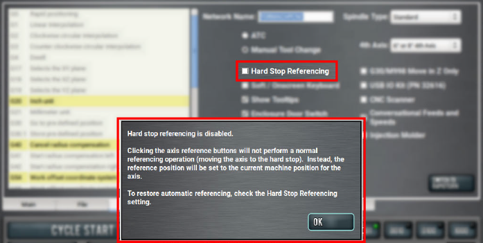
Disable Hard Stop Referencing
To provide a temporary workaround for a malfunctioning limit switch circuit, you can disable the limit switches.
NOTE: By default, the Hard Stop Referencing checkbox is selected.
To disable :
-
From the Settings tab, clear the Hard Stop Referencing checkbox.
-
Select OK.
The machine completes a unique referencing procedure after selecting the axis reference buttons: rather than moving each axis to the end of its travel, the reference position is set as the machine's current position.
Tip! This is useful for troubleshooting, because you're now able to move the axis.
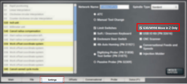
Limit G30 Moves
You can limit G30 moves so that only the Z-axis moves. For information, see "About G30".
To limit G30 moves:
-
From the Settings tab, select G30/M998 Move in Z Only.
About G30
A G30 command in a G-code program moves the machine to a preset position. For more information on setting a G30 position, see "Use a G30 Position".
Use a G30 move to start a coordinated movement of the axes. You can limit the movement to only the Z-axis. For information, see "Limit G30 Moves".
Tip! It's useful to program a G30 move right before a tool change so that the machine can jog to a safe tool change position.
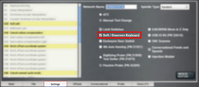
Enable the On-Screen Keyboard
If you have an (optional) Touch Screen Kit (PN 35575), you can use a soft keyboard to type information in the PathPilot interface. For information, see "About Soft Keyboards" (page 23).
To enable and use the soft (on-screen) keyboard:
-
From the Settings tab, select Soft / On-Screen Keyboard.
-
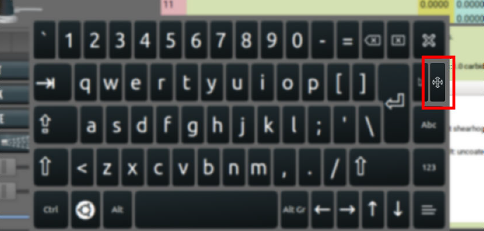
To resize the keyboard, select a corner of the keyboard and drag.
-
To reposition the keyboard, select the Anchor key and drag the keyboard anywhere on the screen.
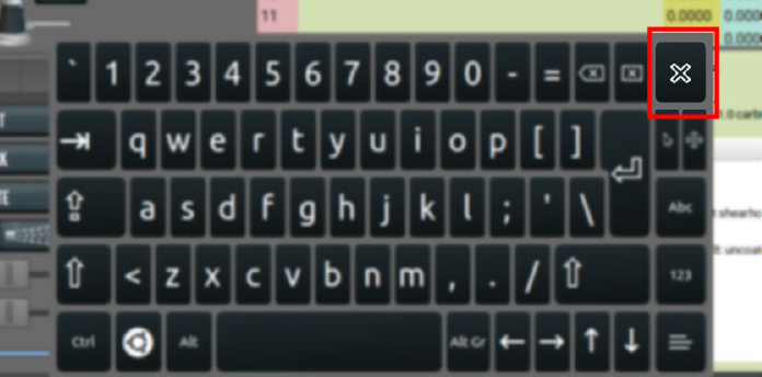
-
To close the keyboard, select the X key.
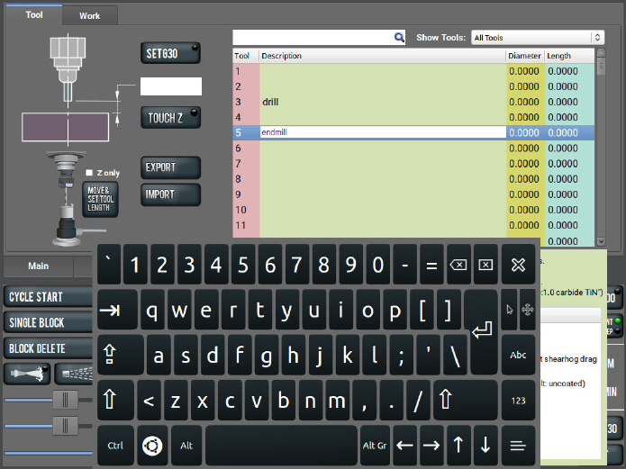
About Soft Keyboards
If you enabled a soft keyboard (on-screen keyboard) in the PathPilot interface to use with an optional touch screen or operator console, a keyboard opens when you select any field where keyboard input is required.
The keyboard displays a wide range of keys: both uppercase and lowercase, symbols, arrow keys, caps lock, backspace and delete, and more.
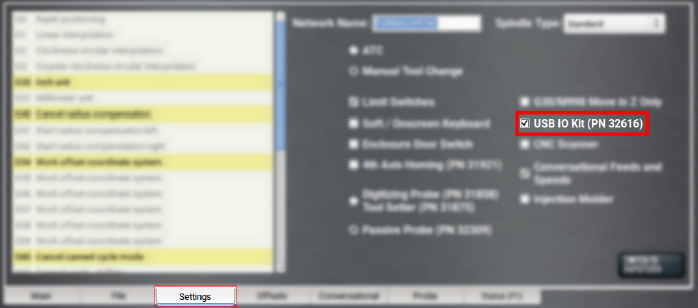
Enable the USB M-Code I/O Interface Kit
If you have a USB M-Code I/O Interface Kit (PN 32616), you must first enable it in the PathPilot interface.
To enable the USB M-Code I/O Interface Kit:
-
From the Settings tab, select USB IO Kit (PN 32616).
Enable Tooltips
PathPilot displays expandable tooltips for many areas of the interface. Hovering over an item, like a DRO field or a button, displays helpful information about the item.
To enable or disable tooltips:
-
From the Settings tab, select or clear Show Tooltips.
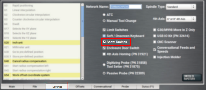
NOTE: If you disable the tooltips, you can still display them for specific items. Hover over an area of the interface, and select the Shift key on the keyboard.
Use a USB Camera
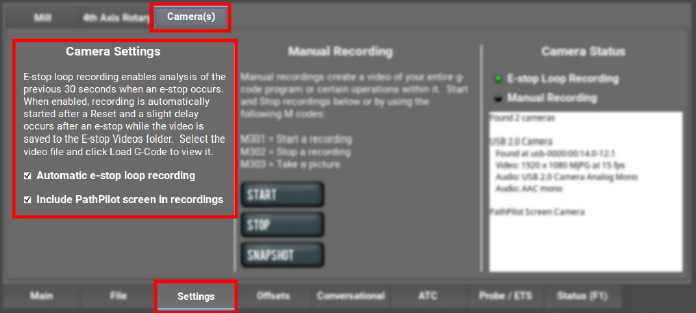
After plugging in the USB camera, navigate to the camera settings. From the PathPilot interface, in the Settings tab, open the Camera(s) tab. Identify the Camera Status read-only dialog box.
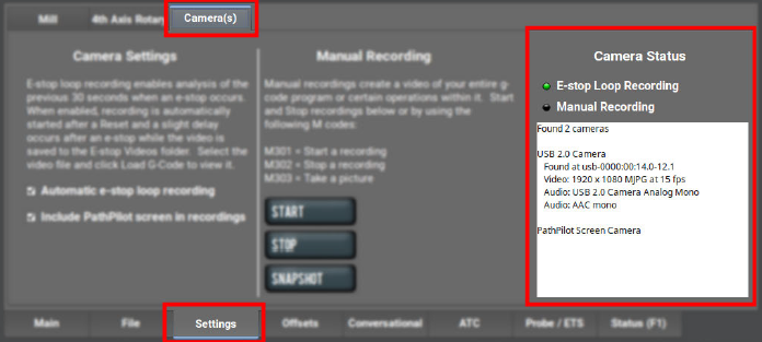
As cameras are plugged in and unplugged, the Camera Status area is refreshed. To test compatibility of any USB camera, plug it in and watch the Camera Status area for the camera name and details.
NOTE: If a camera isn't shown after plugging it in or starting a video recording, it might require too much power from the USB ports on the controller. This is very likely when more than one camera is used. Try using a powered USB hub to add the camera(s).
When a USB camera is plugged in, it's analyzed for supported video and audio formats, frame sizes, and frame rates. If the camera supports it, PathPilot uses H.264 compression; otherwise, it uses Motion JPEG.
If the USB camera has a microphone, PathPilot records audio as well as video. The preferred format is compressed AAC, but uncompressed PCM is used as a fallback.
About USB Cameras
Recording video and audio from USB cameras is supported in PathPilot v2.10.0 and later. You can use up to four cameras simultaneously to record from different vantage points.
NOTE: All cameras are started and stopped at the same time — if you don't want a camera to record, you must unplug it.
USB cameras are compatible with all machine types, but older controllers may lack the processing power and memory needed for camera support. Controllers require 4GB of memory for camera functionality. Use the ADMIN MEMORY MDI command to verify the memory size of a controller.
You can purchase a Tormach USB Camera (PN 51240) with a metal case, mounting bracket, and 15-foot USB cable. Other USB cameras may work (see below), but do not include any technical support.
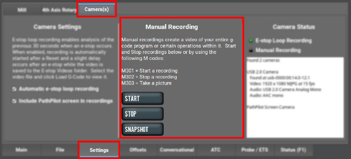
Manual Recording
To start or stop a manual recording, either:
-
Use the controls in the Manual Recording area of the Camera(s) tab.
When a manual recording is stopped, a file save-as dialog appears prompting you for the file name base to use.
-
Select the Video Camera Recording button in the Persistent Controls section.
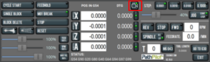
Whenever PathPilot is recording from a USB camera and/or the virtual screen camera, the LED on this button is green. If PathPilot is recording and the button is pressed:
-
If a program is running and not paused at an M00/M01, the recording is aborted.
-
If a program is not running, but the machine is moving, the recording is aborted.
-
Otherwise, if a manual recording is in progress, it is stopped and a file save as dialog will appear. If an automatic e-stop loop recording is in progress, it is aborted since no e-stop occurred.
To include a screen recording:
-
Toggle the Include PathPilot screen in recordings checkbox in the Camera Settings area of the Camera(s) tab to enable or disable screen recording.
To take a picture (using all of the USB cameras at once):
-
Select Snapshot in the Manual Recording area of the Camera(s) tab.
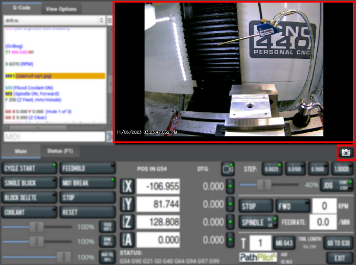
The Main tab displays. -
Review the camera images, which display on top of the Tool Path area. The camera images refresh every 0.5 seconds.
-
Align the cameras or adjust lighting to your preference, and then select the Shutter button.
Automatic E-Stop Loop Recording ("Dashcam")
E-stop loop recording enables analysis of the previous 30 seconds after an E-stop. When enabled, recording is automatically started after reset.
To enable or disable the recording of emergency stops:
-
Toggle the Automatic e-stop loop recording checkbox in the Camera Settings area of the Camera(s) tab.
NOTE: This feature is enabled by default.
Automatic E-stop loop recording starts when the Reset button is selected. If you selected Video Camera Recording to abort a previous E-stop loop recording, select Reset to start it again.
To view E-stop videos:
-
A slight delay occurs after an E-stop while the video is saved to the E-stop Videos folder. Select the video file, and then select Load G-Code to view it.
NOTE: The E-Stop Videos folder is automatically monitored for internal drive space use. If the folder size grows beyond 5 GB, the oldest video files are automatically deleted until the folder size becomes less than 5 GB.
Review Video and Image Files
-
On the File tab, select the video or image file and select Load G-Code.
A video player application starts or the image preview is displayed.
Alternatively, you could transfer the video or image files to a Windows or macOS computer for review.
File Naming Convention
For manual and automatic E-stop recordings, the base file name for the recording has automatically chosen suffixes appended for each camera.
For example, if you stop a manual recording of two cameras, specify “Left Bracket Op1” as the name, and enabled screen recording, you'll see the following files:
|
File Name |
Description of File |
|
Left Bracket Op1_0.mp4 |
Camera 0 mp4 video file |
|
Left Bracket Op1_0.log |
Troubleshooting log for camera 0 |
|
Left Bracket Op1_1.mp4 |
Camera 1 mp4 video file |
|
Left Bracket Op1_1.log |
Troubleshooting log for camera 1 |
|
Left Bracket Op1_PP.mp4 |
PathPilot screen recording mp4 video file |
|
Left Bracket Op1_PP.log |
Troubleshooting log for screen recording |
G-Code Commands
PathPilot supports three new M-codes to control cameras within G-code programs: M301, M302, and M303. Example use cases:
-
Record only across each M01 stop where the operator needs to flip a workpiece or change a tool.
-
Create short videos that focus on unique aspects of the program to reduce later video editing.
-
Record USB IO integration operations with robots or other devices (pneumatic vises, etc.).
-
Monitor progress on a workpiece by including M303 throughout the program.
File Naming Conventions
Recordings or pictures created by M301/M302/M303 have automatically generated file names, with the base file name taken from the running G-code file. Video files are saved alongside the G-code file. The suffix for each file uses a time stamp format. This makes it easy to distinguish multiple runs of the same G-code program.
For example, if engrave.nc is running and uses M301 and M302 to create one recording on a machine with one camera, and screen recording is enabled, you'll see the following files:
|
File Name |
Description of File |
|
engrave_2023-02-21_16_58_33_0.mp4 |
Camera 0 mp4 video file |
|
engrave_2023-02-21_16_58_33_0.log |
Troubleshooting log for camera 0 |
|
engrave_2023-02-21_16_58_33_PP.mp4 |
PathPilot screen recording mp4 video file |
|
engrave_2023-02-21_16_58_33_PP.log |
Troubleshooting log for screen recording |
|
engrave_2023-02-21_17_43_22.jpg |
Picture taken by a single M303 later in the program |
Use M01 to Take Pictures
In addition to displaying information like pictures or messages during an M01 break, you can also use a USB camera (if installed) to take a picture.
To use M01 to take pictures:
-
Add M01 (op1_setup.jpg) into your G-code program.
-
Run the G-code program.
-
When PathPilot executes the M01 it looks to see if the comment contains a file name.
-
If there isn't a file name: The comment is shown as instructional text across the tool path.
-
If there is a file name, but the file doesn’t exist yet and the extension is .jpg, .png, or .jpeg: The USB cameras are initialized and shown in the tool path display.
-
Select the Shutter button to take the picture and create the op1_setup.jpg file.
In future runs of the G-code program, op1_setup.jpg will display to the operator for instructional purposes on the workpiece.
For more information, see “Display Information and Capture Images During an M00 or M01 Break”.
Set Up G-Code Programs
Before running a G-code program, you must first make sure that the machine is properly set up for the specific G-code program.
Set Work Offsets
To set the current axis location to zero in the active work coordinate system:
-
Select Zero [Axis].

To change work offsets:
-
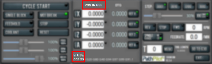
On the Main tab, in the MDI Line DRO field, type the new work offset to activate (for example, G55). Then select the Enter key.
-
The new work offset displays in the following locations in the PathPilot interface:
-
The Status read-only DRO field.
-
Above the Work Offset DRO fields.
NOTE: The values in the Work Offset DRO fields update to indicate the new location of each axis in the new work offset.
For more information on using work offsets, see "About Work Offsets".
About Work Offsets
Work offsets allow you to think in terms of X, Y, and Z coordinates with respect to the part, rather than thinking of them with respect to the machine position. This means that you can jog the machine to an arbitrary location (like the end of a workpiece) and call that location zero.
You can save up to 500 work offsets in PathPilot. The naming structure varies based on the offset number, as detailed in the following table.
|
Work Offset Naming |
||
|
Offsets 1-9 (Use either name) |
||
Offset
|
Extended Name
|
Name
|
|
1 |
G54.1 P1 |
G54 |
|
2 |
G54.1 P2 |
G55 |
|
3 |
G54.1 P3 |
G56 |
|
4 |
G54.1 P4 |
G57 |
|
5 |
G54.1 P5 |
G58 |
|
6 |
G54.1 P6 |
G59 |
|
7 |
G54.1 P7 |
G59.1 |
|
8 |
G54.1 P8 |
G59.2 |
|
9 |
G54.1 P9 |
G59.3 |
|
Offsets 10-500 (Use extended name) |
||
|
Offset |
Extended Name |
Name |
|
10 |
G54.1 P10 |
Not used |
|
11 |
G54.1 P11 |
Not used |
|
... |
||
|
499 |
G54.1 P499 |
Not used |
|
500 |
G54.1 P500 |
Not used |
View Work Offsets
To view the current work offset:
-
From the Offsets tab, on the Work tab, identify the Work Offsets Table window.
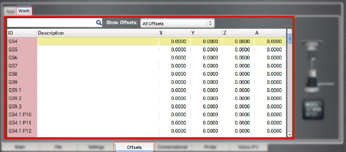
The active work offset is highlighted.
To change the current work offset, go to "Set Work Offsets".
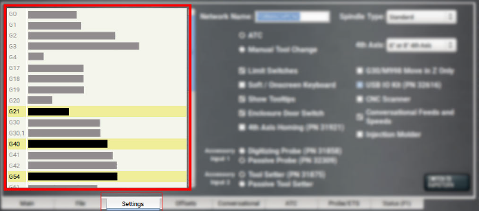
View Available G-Code Modes
The G-Code Description window shows a list of all available G-code modes.
To view available G-code modes:
-
From the Settings tab, find the G-Code Description window.
Run G-Code Programs
While running a G-code program, use the following controls:
Bring the Machine Out of Reset
-
Select Reset.
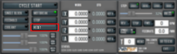
For more information on reset mode, see "About Reset Mode".
About Reset Mode
When the machine is first powered on, or after an emergency stop, the Reset button flashes. When you select the flashing Reset button, PathPilot verifies communication to the machine and does the following activities:
-
Brings the machine out of an emergency stop condition
-
Clears alarms
-
Clears the tool path backplot
-
Resets all modal G-codes to their normal state
-
Rewinds the currently loaded G-code program
-
Stops machine motion, but is not a replacement for the Emergency Stop button
You can select the Reset button any time while the machine is on.
View the Active Axis to Jog
To find which axis is active while jogging your machine:
-
Identify the light next to the Work Offset DRO fields.
For information, see "Jog the Machine".
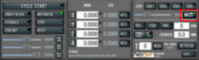
Jog the Machine
To switch between jogging modes:
-
From the Manual Control area, in the Jog group, select Jog.
PathPilot toggles between continuous velocity mode and step mode.
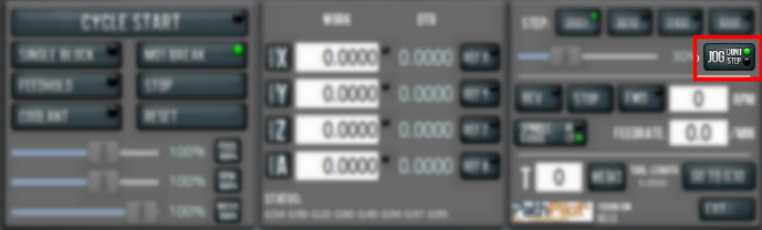
When the Cont green light is on, continuous velocity mode is selected.
When the Step green light is on, step mode is selected.
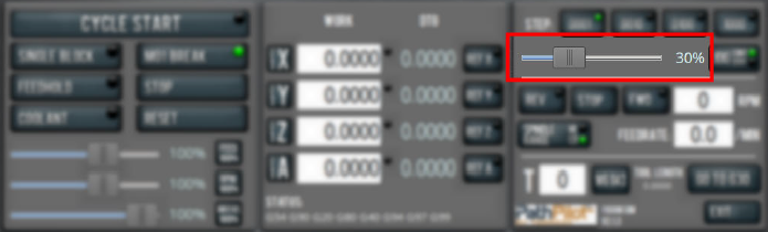
To use continuous velocity mode:
-
Set the velocity: drag the Jog Speed slider.
For more information on continuous velocity mode, see "About Continuous Velocity Jogging".
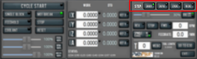
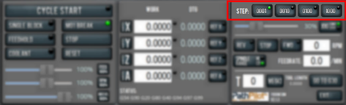
To use step mode, select the step size. Do one of the following, depending on your accessories:
-
In the Manual Control Area, in the Jog group, select the step size.
The Step button's light comes on, indicating which step size is active.
-
On the (optional) Jog Shuttle, press the Step button to toggle the currently selected step size.
In the PathPilot interface, the Step button's light comes on, indicating which step size is active.
For more information on step mode, see "About Step Jogging".
Jog in Continuous Velocity Mode
In continuous mode, the machine jogs at a continuous velocity.
To select continuous velocity mode:
-
In the Manual Control area, select Jog.
When the Cont green light is on, continuous velocity mode is selected.
When the Step green light is on, step mode is selected.
To set the velocity:
-
Drag the Jog Speed slider.
About Continuous Velocity Jogging
While jogging in continuous velocity mode, the machine moves at a constant speed for as long as:
-
A keyboard key is pressed
-
The Jog Shuttle outer ring is twisted away from the neutral position
This is useful when you're doing things like:
-
Roughly positioning the machine (for example, to move the spindle head away from the workpiece).
-
Moving the machine a certain distance at a constant speed.
Jog in Step Mode
In step mode, the machine jogs in steps, which range based on the programming mode you're using:
-
Imperial (G20) Mode 0.0001 in. to 0.1000 in.
-
Metric (G21) Mode 0.01 mm to 10 mm
To select the step size:
-
In the Manual Control Area, select the step size.
The Step button's light comes on, indicating which step size is active.
About Step Jogging
While jogging in step mode, the machine moves one step each time you either press a jog key on the keyboard or click the inner wheel of the Jog Shuttle. The jog step sizes range depending on the programming mode you are using:
-
Imperial (G20) Mode 0.0001 in. to 0.1000 in.
-
Metric (G21) Mode 0.01 mm to 10 mm
Step jogging mode is useful to finely move the machine, like when you're indicating a workpiece or manually setting tool lengths.
The jog keys on the keyboard only move the machine in steps when step mode is indicated in PathPilot. The inner wheel on the jog shuttle always moves the machine in steps, regardless of which mode is indicated in PathPilot.
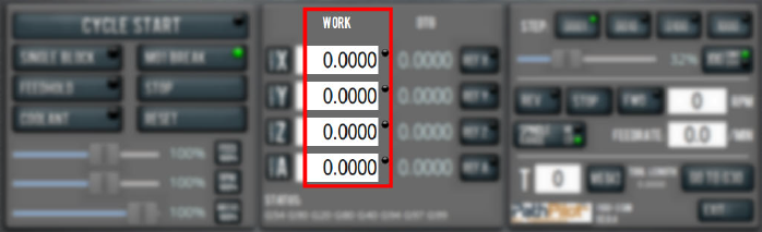
View the Current Machine Position
-
Identify the Work Offset DRO fields.
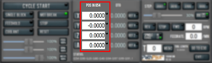
The position is expressed by the currently active work offset coordinate system (like G54 or G55).
When the machine isn't moving, you can edit the DRO fields. For more information on setting work offsets, go to "Set Work Offsets".
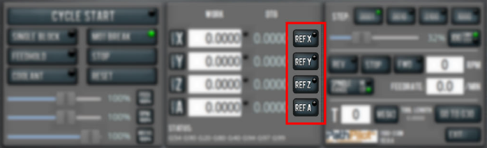
Reference the Machine
-
Verify that the machine can freely move to its reference position (at the ends of travel).
-
To verify that the tooling is clear of any possible obstructions, reference the Z-axis before referencing the other axes: from the PathPilot interface, select Ref Z.
-
Once the spindle is clear of any possible obstructions, continue referencing all axes.
NOTE: You can select the buttons one after another. Once the machine references one axis, it'll move on to the next.
After each axis is referenced, its button light comes on.
For more information on referencing the machine, see "About Referencing".
About Referencing
You must reference the machine to establish a known position for PathPilot. The position that's set while referencing the machine is the origin of the machine coordinate system. Without referencing the machine, PathPilot won't know the current position of the machine axes.
You must reference the machine at the following times:
-
After you power on the machine
-
After you push in the Emergency Stop button
-
Before running a G-code program
-
Before using MDI commands
-
Before setting work or tool offsets
-
After a collision or an axis stall/fault
When referencing, the machine moves each axis to the end of its travel. The machine stops at the limit switch, which sets the axis’ reference position.
Start a Program
-
From the PathPilot interface, in the Main tab, select Cycle Start.
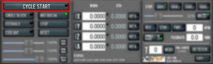
For more information on starting a program, see "About Cycle Start".
If you can't start a program, go to "Cycle Start Reference".
About Cycle Start
While a program is running, the Cycle Start button's light is on.
The Cycle Start button's light flashes if motion is paused during the program. The following modes may pause motion during a program:
-
Single block
-
Feed hold
-
M01 break
If machine motion pauses a single block, feed hold, or M01 break, the Cycle Start button flashes until it's selected again.
Cycle Start Reference
The Cycle Start button doesn't operate if you select it:
-
While you're not in the Main tab. For information, see “Main Tab” Reference.
-
Before you've loaded a G-code program. For information, see "Load G-Code".
-
Before referencing the machine. For information, see "Reference the Machine".
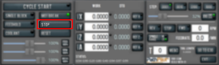
Stop Machine Motion
-
From the Program Control area, select Stop.
View the Active G-Code Modes
To find the currently active G-code modes and the currently active tool at a glance:
-
Identify the Status read-only DRO field.
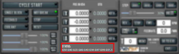
For more information on G-code modes, go to "View Available G-Code Modes".
View the Distance to Go
To view the distance to go:
-
Identify the DTG read-only DRO fields.
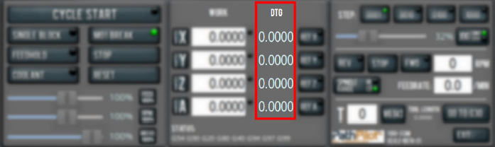
The value is the remaining distance in any programmed move.
For more information on using the DTG read-only DRO fields, see "About Distance to Go".
About Distance to Go
While a program is running, the DTG read-only DRO fields show the remaining distance in each move.
After using the feed hold function or the maxvel override function, look at the distance to go. This read-only DRO field is useful to prove out a part program.
Control G-Code Programs
If necessary, use the following controls to add to your G-code program:
Use the Feed Hold Function
-
Select Feed Hold.
Tip! Use the Spacebar key to quickly activate the feed hold function.
For more information on using the feed hold function, see "About Feed Hold".
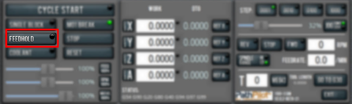
About Feed Hold
When the feed hold function is active, the Feed Hold button's light is on.
The feed hold function pauses machine motion — aside from the spindle — and the Cycle Start button flashes. For information, see "About Cycle Start".
NOTE: If the machine isn't moving, the feed hold function doesn't have an effect.
You can use the feed hold function either while a program is running or while you are using manual data input (MDI) commands. If the program is running a spindle-synchronized move, the feed hold function is delayed until the move is complete.
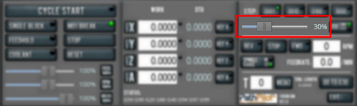
Use the Feed Rate Override Function
To use the feed rate override function:
-
Using the Feed Rate Override slider, change the programmed feed rate by a specific percentage.
NOTE: Percentages range from 1-200%.
To remove the feed rate override function:
-
Select Feed 100%.
The feed rate returns to 100% of its programmed value (it's no longer overriden).
For more information on the feed rate override function, see "About Feed Rate Override".
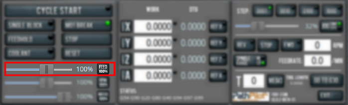
About Feed Rate Override
You can use the feed rate override function while you're doing any of the following activities:
-
Using manual data input (MDI) commands
-
Jogging
-
Running a program with G01, G02, or G03 commands
The feed rate override function does not affect G00 (rapid) commands. It's ignored if:
-
The program is running a spindle-synchronized move
-
An M48 (disable feed and speed overrides) command is used
To indicate lack of motion or unusual levels, the slider turns yellow when it's either at 0% or above 100%.
The Feed Rate Override slider and Feed 100% button work similarly to the spindle override controls. They affect the commanded feed rate by a percentage from 1-200%. The feed rate override works for MDI, jogging, and G-code program G01/G02/G03 moves. The override has no effect on G00 (rapid) moves.
Use M01 Break Mode
-
Select M01 Break.
For more information on using M01 break mode, see "About M01 Break".
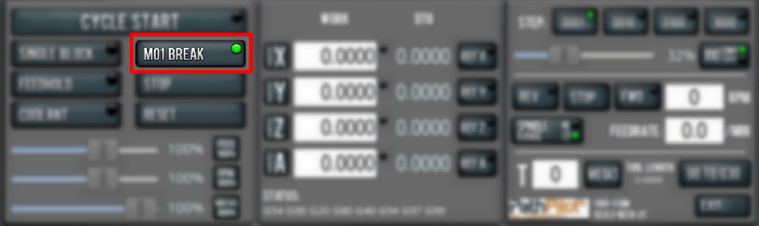
About M01 Break
When the M01 break mode is active, the M01 Break button's light is on. When the M01 break mode is inactive, the M01 Break button's light is off.
M01 break mode enables any M01 (optional stop) commands that are programmed in the G-code file. You can turn M01 break mode on or off either before starting a program or while a program is running.
-
When M01 Break is Active Machine motion stops after PathPilot reaches an M01 command, and the Cycle Start button flashes. For information, see "About Cycle Start".
-
When M01 Break is Inactive PathPilot ignores all programmed M01 commands.
Use the Maxvel Override Function
To use the maxvel override function:
-
Using the Maxvel Override slider, change the maximum velocity by a specified percentage.
To remove the maxvel override function:
-
Select Maxvel 100%.
For more information on using the maxvel override function, see "About Maxvel Override".
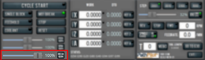
About Maxvel Override
The maxvel override function affects G00 and G01 commands, and it's useful for:
-
Running a Program for the First Time Drag the Maxvel Override slider to 0% to verify that all DRO fields look appropriate.
-
Safety If you're running a spindle-synchronized move, a maxvel override isn't ignored.
Verify that the maxvel override value allows the machine to use the programmed feed rate during spindle-synchronized moves. If it can't, the spindle-synchronized move won't produce the results you want.
To indicate lack of motion or unusual levels, the slider turns yellow when it's either at 0% or above 100%.
Use Single Block Mode
-
Select Single Block.
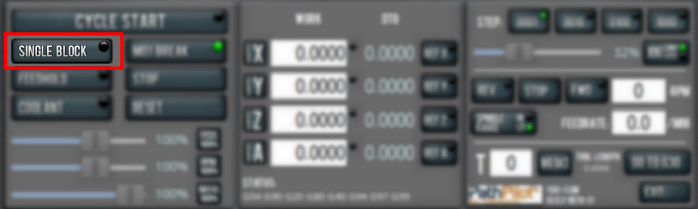
For more information on using single block mode, see "About Single Block".
About Single Block
While single block mode is active, the Single Block button's light is on.
Single block mode runs one line of G-code at a time. After each line, motion is paused, and the Cycle Start button flashes. For information, see "About Cycle Start".
You can turn single block mode on or off either before starting a program or while a program is running. For information, see "Use Single Block Mode".
NOTE: Single block mode ignores non-motion lines, like comment lines or blank lines.
Use the Voltage Override Function
To use the voltage override function:
-
Using the Voltage Override slider, change the programmed voltage by a specific percentage.
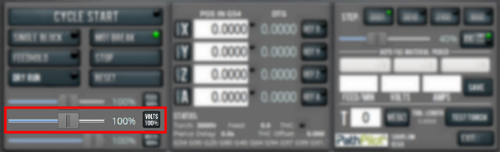
NOTE: Percentages range from 1-200%.
To remove the voltage override function:
-
Select Volts 100%.
The voltage returns to 100% of its programmed value (it's no longer overridden).
Change the Tool Number
The Tool DRO field shows the tool number currently active.
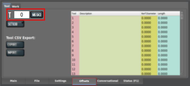
To change the tool number (and apply its tool length offset):
-
In the Tool DRO field under the Offsets tab, type a number (the valid range is from 0-1000). Then select the Enter key.
NOTE: You can also select M6 G43. For information, see "About M6 G43".
About M6 G43
The M6 G43 button is a shortcut used to do the following:
-
Change the number of the currently-loaded tool in the spindle to the number typed in the Tool DRO field. This is the equivalent of an M06 command.
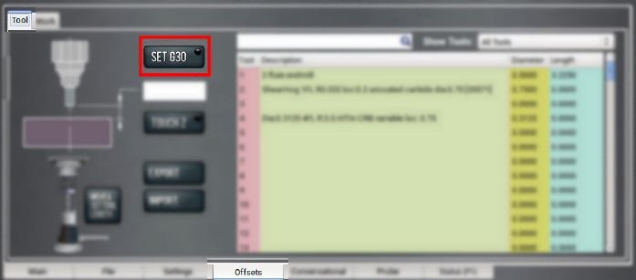
Use a G30 Position
The Go to G30 button moves the machine to a predefined G30 position. For information, see "About G30".
To set a G30 position:
-
Jog the machine to the desired G30 position.
-
From the Offsets tab, select Set G30.
To go to a set G30 position:
-
Use a G30 command in a G-code program or in the MDI Line DRO
NOTE: The G30 position defaults to only moving the Z-axis.
About G30
A G30 command in a G-code program moves the machine to a preset position. For more information on setting a G30 position, see "Use a G30 Position".
Use a G30 move to start a coordinated movement of the axes. You can limit the movement to only the Z-axis. For information, see "Limit G30 Moves".
Manually Enter Commands
You can send G-code commands directly to the machine by using the MDI Line DRO field. For information, see "About the MDI Line DRO Field".
To manually enter commands:
-
Select the MDI Line DRO field.
The DRO field highlights.
-
Type the command.
NOTE: You can use the Backspace, Delete, Left Arrow, and Right Arrow keys to correct typing errors.
-
You must press the Enter key to execute the command. To abandon the command, press Esc.
About the MDI Line DRO Field
The MDI Line DRO field allows you to send commands (or, manual data input) directly to PathPilot. For information, see "Manually Enter Commands".
The MDI Line DRO field saves up to 100 of your most recent commands, which are saved after a power cycle.
When you select the MDI Line DRO field, all keystrokes are used within the field — so, you can't jog the machine.
Admin Commands Reference
Use the following commands in PathPilot:
|
Admin Command |
Use to... |
|
Admin Audio |
Customize the controller's audio device settings. |
|
Admin Calc |
Open the calculator. |
|
Admin Clear |
Clear the message history on the Status tab. |
|
Admin Config |
Change the configuration of the PathPilot interface. |
|
Admin CycleCounter |
Control the cycle counters in the Tool Path display. |
|
Admin Date |
Customize the controller's date and time. |
|
Admin Display |
Customize the controller's screen display. |
|
Admin Dropbox |
Connect your controller to a Dropbox account for cloud file syncing. |
|
Admin Help |
Review a list of available Admin commands. |
|
Admin Keyboard |
Customize the controller's keyboard layout. |
|
Admin Logdata |
Write the latest machine log data to a USB drive for technical support assistance. |
|
Admin Memory |
Determine how much total RAM is on your controller. |
|
Admin Mouse |
Change the mouse preferences, like pointer speed and right- or left-hand button mapping |
|
Admin Network |
Configure a Wi-Fi network. |
|
Admin Reset_Soft_Limits |
Reset axis soft limits to machine defaults. |
|
Admin Set_X_Limit |
Set the X-axis soft limit. |
|
Admin Set_Y_Limit |
Set the Y-axis soft limit. |
|
Admin Set_Z_Limit |
Set the Z-axis soft limit. |
|
Admin Settings Backup |
Create a backup of tool offset and fixture information to store externally. |
|
Admin Settings Restore |
Restore tool offset and fixture information backup from an external location. |
|
Admin Show_Soft_Limits |
Display the current axis soft limits on the Status tab. |
|
ADMIN TOOLTIP DELAYMS |
Set the milliseconds prior to displaying the tooltip (and then again for the expanded tooltip). The default is 1200 milliseconds. |
|
ADMIN TOOLTIP MAXDISPLAYSEC |
Limit the amount of time the expanded tooltip displays. The default is 15 seconds. |
|
Admin Touchscreen |
Adjust the touch screen calibration. |
|
Admin Version |
Display detailed version information on the Status tab. |
Copy Recently Entered Commands
-
From the MDI Line DRO field, press either the Up Arrow key or the Down Arrow key.
The previously entered command displays. -
You must press the Enter key to execute the command. To abandon the command, press Esc.
For information, see "Manually Enter Commands".
Use the AutoFS Material Picker
PathPilot on the 1300PL is designed so that you don't need to manually program feeds and speeds in your G-code. Instead, feed rate, amperage, pierce parameters, and torch height control voltage are all set at program run-time using automatic look-up tables based on the material you're cutting.
AutoFS is designed so that you can export a program once from your post-processor and run it multiple times with different materials, all without re-posting. All material-specific machine parameters are set by the M200 AutoFS M-code (rather than directly programmed in the G-code).
Writing G-Code with AutoFS
A standard block of G-code before a cutting operation might look like this:
M210 P123 (Set THC voltage to 123v)
M211 P45 (Set plasma source to 45A)
M207 P0.15 (Set pierce height to 0.15")
M208 P0.08 (Set cut height to 0.08")
M209 P2 (Set a two second pierce delay)
F225 (Set cutting feed rate of 225 IPM)
G15 (Perform ohmic probe)
G16 (Pierce and start cutting)
The block of code shown above is totally valid and can be used if you prefer to hard code your cutting parameters. Alternatively, the code shown above can be replaced with the following when AutoFS is being used:
M200 (Set cutting parameters from AutoFS tables)
G15 (Perform ohmic probe)
G16 (Pierce and start cutting)
Using AutoFS
-
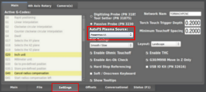
On the Settings tab, select which plasma source you're using from the Auto FS Plasma Source drop-down menu.
-
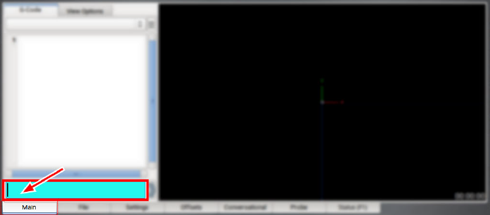
Before running your program, select the material you're cutting from the AutoFS dropdowns on the Main tab of PathPilot.
The DROs turn green, which indicates that they were automatically set.
With a material selected, the next time an M200 code is encountered in a program, PathPilot will set all of the cutting parameters for that material.
Creating Custom AutoFS Presets
Since your shop air supply and cutting conditions might differ from those used to create the AutoFS presets, you can save your own custom settings for a material at any time.
To create new AutoFS presets:
-
From the Main tab, select the material you're cutting from the AutoFS dropdowns, and then type your cut parameters into the DRO fields.
-
Select Save.
The values are stored as a new preset for that material.
Deleting Custom AutoFS Presets
-
From the File tab, navigate to the fs_tables folder, and open the plasma_user_fs_data.csv file.
-
Highlight the line of the preset you want to delete and delete it. Then, save the file.
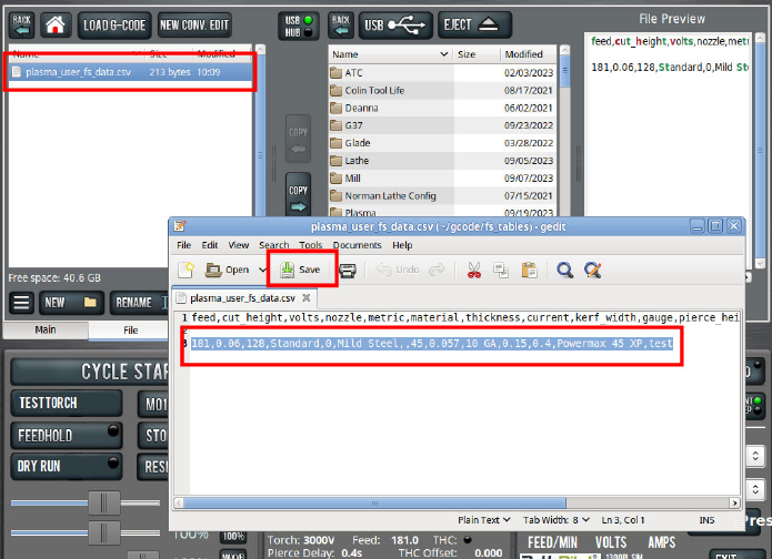
NOTE: This file is read on boot only, so the preset remains visible until the controller is power cycled.
Use Cycle Counters (M30 and M99)
On the Main tab, the Tool Path display shows M30 and M99 cycle counters. They're useful to count parts completed during unattended operation. For each M-code, there's an A and B counter. This provides more flexibility, because you can reset them to 0 independently.
For example, you could use M30 A to count parts each shift, and M30 B to count parts each week. The cycle counters persist across the controller's power cycles.
Monitor Cycle Counters
-
In the MDI Line DRO field, type ADMIN CYCLECOUNTER to show or hide the counters and to reset them to 0.
Change Cycle Counter Values
The cycle counters are implemented as read-only persistent G-code numbered parameters, as detailed in the following table. If needed, the cycle counter value can be read in G-code.
|
Cycle Counter |
Parameter |
|
M30 A |
#5650 |
|
M30 B |
#5651 |
|
M99 A |
#5652 |
|
M99 B |
#5653 |
To change a counter value explicitly, use a G10 command: G10 L99 P~ Q~
-
P~ selects the cycle counter to change. Use any of the values detailed in the following table.
|
Cycle Counter |
P~ |
|
M30 A |
0 |
|
M30 B |
1 |
|
M99 A |
2 |
|
M99 B |
3 |
-
Q~ specifies the value to set the cycle counter. If Q~ is omitted, the cycle counter is incremented by 1.
For example, if you program G10 L99 P2, the M99 A cycle counter increments by 1.
System File Management
To keep the files on your system backed up and organized, use the following controls:
Manage System Files
Use the File tab to manage system files on the PathPilot controller. For information, see "Transfer Files to and From the Controller".
To manage system files:
-
From the PathPilot interface, on the File tab, do any of the following from the Controller Files window:
-
Select a file, and then select New Folder, Rename, or Delete.
-
Select a file, and go to the Options menu. Then, select Copy, Cut, or Paste.
-
To navigate through the system files:
-
Select Back or Home.
Create Backup Files
-
Insert a blank, formatted USB drive into the PathPilot controller.
NOTE: To prevent errors when backing up and restoring files, only use a blank, formatted USB drive.
-
From the PathPilot interface, on the Main tab, in the MDI Line DRO field, type ADMIN SETTINGS BACKUP. Then select the Enter key.
PathPilot generates a backup .zip file, and the Admin Settings Backup dialog box displays.
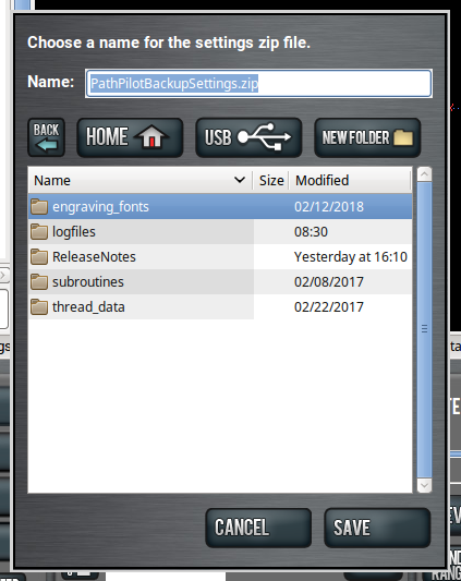
-
From the Admin Settings Backup dialog box, specify where (on the PathPilot controller or on a USB drive) to save the backup .zip file.
-
Select Save.
The backup .zip file is saved in the location you specified in Step 3. -
If you saved the backup .zip file on the PathPilot controller, you must manually transfer it — along with other files you want to back up (like G-code programs) — to a USB drive. From the PathPilot interface, on the File tab, in the Controller Files window, select the backup .zip file and any other files you want to back up.
NOTE: Files must have unique names. If they don't, PathPilot prompts you to overwrite or rename files, or cancel the file transfer.
-
To prevent errors, make sure you don't include the following folders:
-
logfiles
-
media
-
ReleaseNotes
-
subroutines
-
USB
-
Select Copy to USB.
The files are copied and display in the USB Files window. -
Eject the USB drive from the PathPilot controller.
-
From the PathPilot interface, select Exit.
-
Verify that all files are properly saved: insert the USB drive on a device other than the PathPilot controller, and review the list of files on the USB drive.
-
(Optional) As an extra precaution, copy all the files onto the device.
About Backup Files
Make a regular backup of all tool offset and fixture information and machine settings stored on your PathPilot controller. Store the file externally to use if you replace your controller or restore it to factory settings.
Restore Backup Files
-
Insert the USB drive with your backup files into the PathPilot controller.
-
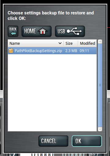
From the PathPilot interface, on the Main tab, in the MDI Line DRO field, type ADMIN SETTINGS RESTORE. Then select the Enter key.
The Admin Settings Restore dialog box displays.
-
From the Admin Settings Restore dialog box, navigate to the backup .zip file on the USB drive, and then select OK.
The PathPilot operating system restores the backup, then restarts. -
If you backed up any other files onto the USB drive, you must manually transfer the files to the PathPilot controller. From the PathPilot interface, on the File tab, in the USB Files window, select the files you want to transfer.
NOTE: To navigate backward, select Back. To navigate to the top level, select USB.
-
From the Controller Files window, select the folder into which you want to copy the files.
-
Select Copy From USB.
The files display in the Controller Files window.
NOTE: Files must have unique names. If they don't, PathPilot prompts you to overwrite or rename files, or cancel the file transfer.
Import and Export the Tool Table
You can manage the tool table using an external .csv file.
Import a .csv File
-
Transfer the .csv file to a USB drive.
-
Insert the USB drive into the PathPilot controller.
-
Confirm that the PathPilot controller is on.
-
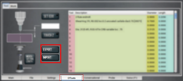
From the Offsets tab, select Import.
The Import dialog box displays.
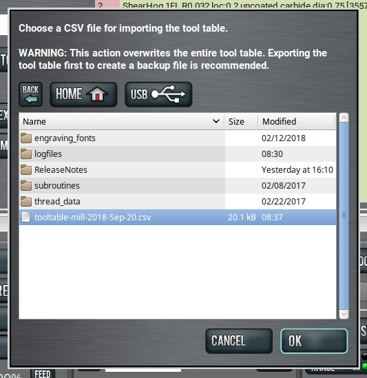
-
Navigate to the .csv file on the USB drive. Then, select OK.
The .csv file updates the tool table.
Export the Tool Table as a .csv File
-
From the Offsets tab, select Export.
PathPilot generates the .csv file, and the Export dialog box displays.
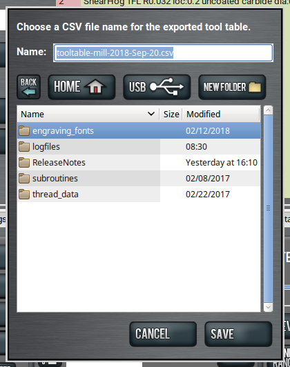
-
In the Name DRO field, type the name for the .csv file.
-
Select Save.
The .csv file is saved in the File tab. -
From the File tab, select the newly created .csv file, and then select Copy to USB.
-
Select Eject.
It's safe to remove the USB drive from the controller.
Looking for more information?
This is a section of the 1300PL operator's manual. To view the whole manual, go to Tormach document UM10720.
If you have additional questions, we can help. Create a support ticket with Tormach Technical Support at tormach.com/how-to-submit-a-support-ticket for guidance on how to proceed.