Purpose
This document gives instructions on installing the PathPilot Operator Console Assembly for 24R.
Product Information
Product: PathPilot Operator Console Assembly for 24R (PN 51060)
|
Quantity |
Description |
|
1 |
Console Controller (PN 50365) |
|
1 |
Keyboard Tray (PN 50475) |
|
1 |
|
|
1 |
Power Cable (PN 38906) |
|
1 |
Ethernet Cable (PN 38391) |
NOTE: If any items are missing, we can help. Create a support ticket with Tormach Technical Support at tormach.com/how-to-submit-a-support-ticket for guidance on how to proceed.
Before You Begin
-
PathPilot v2.8.1 or Later Required Update to the latest version of PathPilot if you haven't yet done so. For information, see the PathPilot Support Center.
Install the Controller Arm
Tools and Items Required
-
4 mm hex wrench
-
6 mm hex wrench
-
8 mm hex wrench
-
17 mm hex wrench
-
17 mm socket wrench
-
21 mm wrench
-
Dead-blow hammer (or similar)
-
Phillips screwdriver
-
Pry bar
CAUTION! Sharp Objects Hazard: Before opening the shipping crate, you must put on work gloves and safety eyewear that meets ANSI Z87+. If you don't, the shipping crate and steel straps could cut you, causing serious injury.
-
Put on work gloves and eye protection.
-
Open the Controller Arm crate with a pry bar.
-
Find the mounting pad on the machine stand.
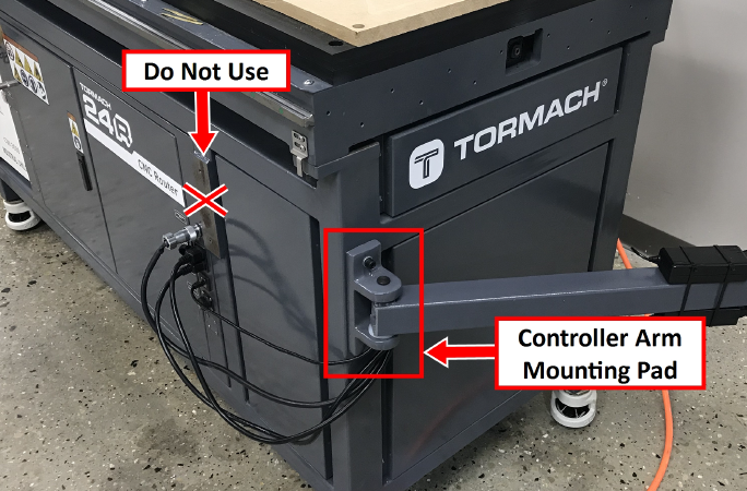
WARNING! Crush Hazard: Only install the Controller Arm on the mounting pad at the front end of the machine. If there's a mounting pad next to the electrical cabinet on the machine stand, don't use it. If you do, there's a risk of entrapment between the Controller Arm and the machine's moving parts.
-
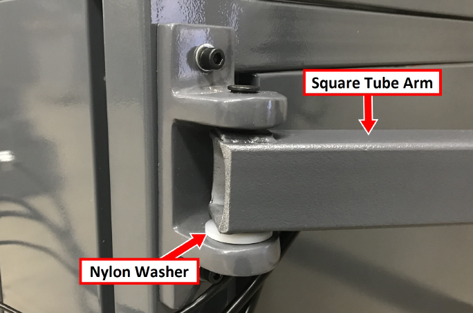
Secure the square tube arm to the machine stand with two M8 socket head cap screws, two M8 flat washers, two M8 lock washers, and a 6 mm hex wrench. Verify that the white nylon washer is located toward the bottom of the mounting pad.
-
Put the monitor post into the square tube arm. Verify that the monitor bracket is toward the top, and that the threaded holes face the holes in the square tube arm.
-
Tighten the cross bolt on the square tube arm with a 17 mm socket wrench and a 17 mm hex wrench.
-
With a 21 mm wrench, remove the monitor bracket from the Controller Arm, and rotate it so that the largest mounting plate is facing up.
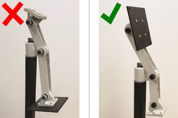
NOTE: The largest mounting plate is for the monitor, and the smallest mounting plate is for the keyboard tray.
-
Tighten the three pivot bolts on the monitor bracket with an 8 mm hex wrench and a 16 mm wrench.
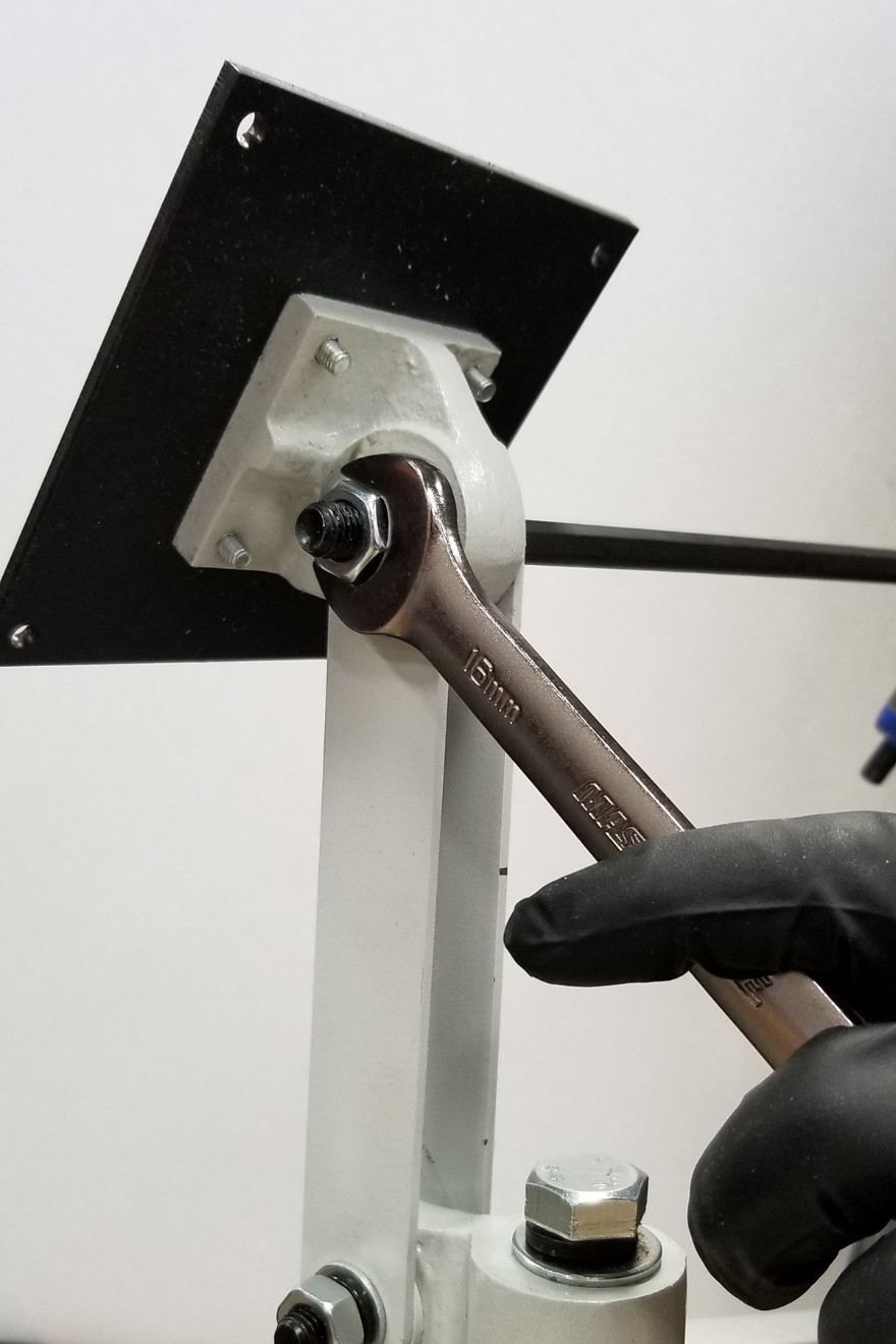
Tip! This makes it easier to install the monitor, which you'll do later in this installation procedure.
-
Tap the end plug into the square tube arm with a dead-blow hammer (or similar).
-
Attach four wire tie mounts to the monitor post with four 4 mm flat head machine screws and a Phillips screwdriver.
Install the PathPilot Operator Console
Tools and Items Required
-
16 mm wrench
-
Metric hex wrench set
-
Phillips screwdriver
-
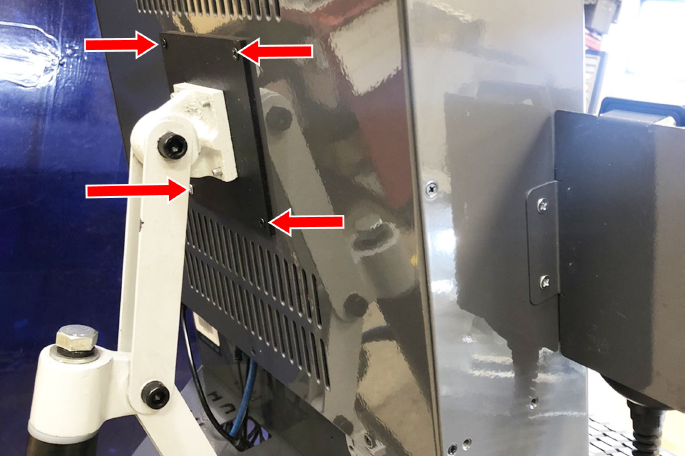
Put the operator console against the monitor mounting plate and align the holes. Attach the operator console and monitor mounting plate together with four M4 × 12 mm socket head cap screws (provided with the operator console).
-
Attach the keyboard tray to the lower controller arm mount with an 8 mm hex wrench.
-
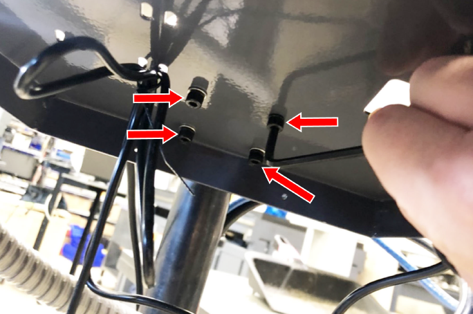
Adjust the operator console and the keyboard tray so that the two holes on the underside of the operator console line up with the holes on the keyboard tray.
-
Attach the keyboard tray to the operator console with two M3 Phillips screws (provided in the controller box) and a Phillips screwdriver.
-
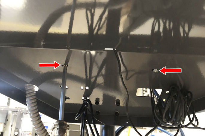
Put the operator console's power supply into the power supply bracket (provided in the operator console box), and attach the assembly to the underside of the keyboard tray with M3 Phillips screws and a Phillips screwdriver.
-
Connect the 12 ft power cable to the power supply.
-
Use the three pivot bolts on the controller arm monitor bracket to adjust the position of the operator console and the keyboard tray to your desired angle with a 3 mm hex wrench and 16 mm hex wrench.
-
If you have any of the following optional USB accessories, connect them to any USB port on the operator console:
-
Jog Shuttle
-
Keyboard
-
Mouse
-
WiFi dongle
-
Connect the WiFi dongle to any USB port on the operator console.
-
Connect the Ethernet cable to the Ethernet port on the operator console.
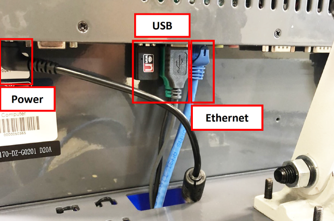
-
Connect the barrel end of the power supply cable to the Power Supply port on the operator console.
-
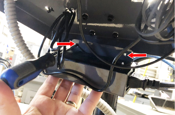
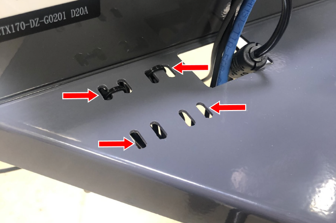
Route the loose ends of the USB, Ethernet, and power supply cables through the square hole in the keyboard tray. Then, use the cable tie holes to secure the loose power supply and USB cables.
Tip! If you're using a mouse, we recommend leaving some slack for it to move freely.
-
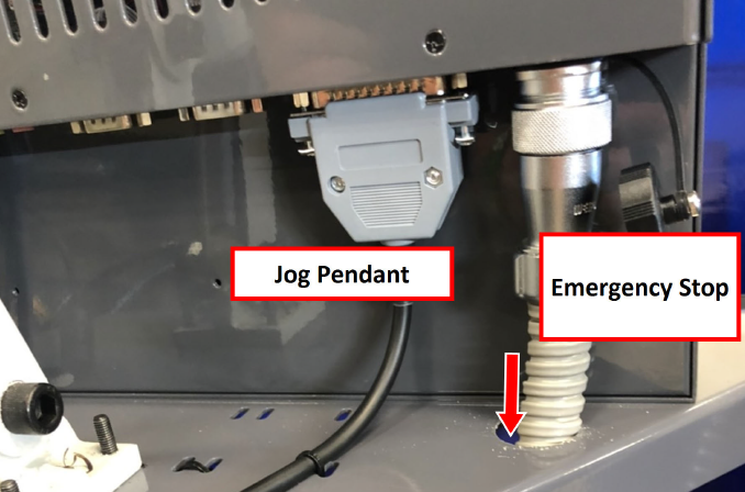
Connect the jog pendant cable and the Emergency Stop cable to the operator console.
-
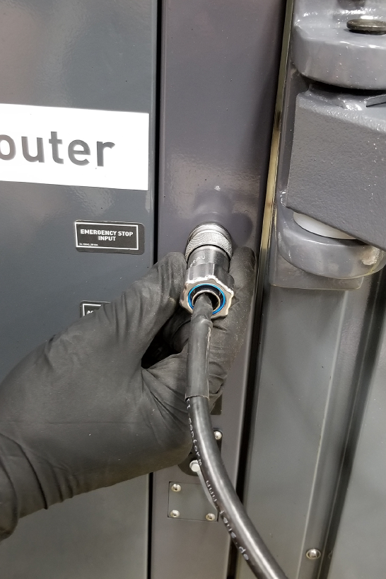
Connect the cable from the operator box to the Emergency Stop Input port on the front right end of the electrical cabinet. Tighten the locking collar to secure the cable.
-
Route the loose end of the operator console's 12 ft power cable, and the Ethernet cable down the controller arm. Then, route the cables through the slots in the square tube arm that's connected to the machine stand.
-
On the right side of the machine, connect the loose ends of the cables as follows:
-
Connect the operator console's power cable to any of the Accessory power outlets.
-
Connect the Ethernet cable to the Controller Communications port.
-
-
Secure the cables to the wire tie mounts that you installed on the round monitor post with four 4 in. cable ties.
Troubleshooting
Problem
The touch screen does not respond to touch inputs on all or part of the screen's surface.
Cause
The sensitivity setting for the touch controller is too low.
Solutions
|
You Might Need To... |
Probability |
How-To Steps |
Need More? |
|
Adjust touchscreen sensitivity. |
High |
Verify that you have PathPilot v2.4.4 or higher installed on your controller. From the PathPilot interface, in the MDI Line DRO field, type ADMIN TOUCHSCREEN SENSITIVITY 1000 and press Enter. You can use a value between 1 and 2047, but 1000 is generally sufficient for most shop spaces. Verify that the touch screen responds to touch inputs. If it doesn't, go to the next step. From the PathPilot interface, on the File tab, find the pointercal.xinput file and delete it. Restart the PathPilot controller. The calibration utility displays. For now, skip this procedure. From the PathPilot interface, in the MDI Line DRO field, type ADMIN TOUCHSCREEN SENSITIVITY 1000 and press Enter. From the PathPilot interface, in the MDI Line DRO field, type ADMIN TOUCHSCREEN and press Enter. The calibration utility displays. Use your finger (not a mouse) to touch all four points that display on the screen. |
The touchscreen is a resistive type to prevent accidental triggering from drops of coolant on the screen. The resistive touchscreen may need its sensitivity adjusted when used in a shop space with very high or low humidity. |
Problem
The console screen doesn't display an image or respond to the power button.
Cause
The console isn't receiving power.
Solutions
|
You Might Need To... |
Probability |
How-To Steps |
Need More? |
|
Examine power input to the console. |
High |
Examine the green LED on the power brick for the console. If it's not lit, examine the power cords to the power brick. |
If your console receives power from the Accessory Input ports on the machine, look for tripped breakers inside your machine's electrical cabinet. |
|
Test the power button functionality. |
Low |
Examine the green ring around the power button. It should light up when you press the power button. |
|
Problem
The console screen turns on, but is scrambled or illegible.
Cause
The BIOS isn't configured for the correct screen output.
Solutions
|
You Might Need To... |
Probability |
How-To Steps |
Need More? |
|
Configure the display output settings in BIOS. |
High |
Connect a VGA monitor to the console. Power the console on and select the Delete key to enter the BIOS. From the Advanced tab, select Display Configuration. Configure the display as follows: Primary IGFX Boot Display: Auto LCD Panel Type: 1280x1024 LVDS Panel Channel: Dual Channel Panel Color Depth: 24 Bit Select the Esc key, go to Save and Exit, and select Save Changes and Reset. |
This configuration problem can occur if your console has a CMOS battery failure. Replace the battery if it reoccurs. |
Problem
The RPM, Feed Override, or Max Velocity knobs don't respond or aren't smooth.
Cause
The ribbon cable connecting the knobs is disconnected or the circuit board is damaged.
Solutions
|
You Might Need To... |
Probability |
How-To Steps |
Need More? |
|
Examine the connectors on the ribbon cable. |
High |
Remove the rear panel of the console. Examine the connectors on both ends of the cable going from J4 on the control board to the potentiometer board. |
Shipping can sometime cause connectors to become loose. Re-seating the connectors will usually fix non-responsive override knobs. |
|
Examine the USB connection to the control board. |
High |
Remove the rear panel of the console. Examine the USB cable going from the header on the computer motherboard to connector J12 on the control board. |
Verify that the power LED on the console control board lights up when the console is turned on. If it doesn't light up, and you have confirmed the USB connection, replace the control board (PN 39146). |
Problem
The Cycle Start or Feed Hold buttons don't respond.
Cause
The control board is disconnected or the wires to the buttons are loose.
Solutions
|
You Might Need To... |
Probability |
How-To Steps |
Need More? |
|
Examine the wiring to the buttons. |
High |
Remove the rear panel of the console. Examine the wire inputs to connector J13 on the control board. If any wires are loose, tighten the screw terminals. Using a continuity tester, measure the resistance between terminals 1 and 2 when Feed Hold is pressed and 3 and 4 when Cycle Start is pressed. If there's continuity at the terminals on the control board and the buttons still don't work, examine the USB cable to the control board. If there's not continuity at the terminals when the buttons are pressed, remove the lower rear panel of the console and examine the screw terminals on the rear of the buttons themselves. |
Shipping can sometime cause wire terminals to become loose. Re-seating the wires will usually fix non-responsive buttons. If you have tested all terminals and the buttons still don't have continuity when pressed, replace the buttons: Feed Hold Button (PN 37363) Cycle Start Button (PN 37362) |
|
Examine the USB connection to the control board. |
High |
Remove the rear panel of the console. Examine the USB cable going from the header on the computer motherboard to connector J12 on the control board. |
Verify that the power LED on the console control board lights up when the console is turned on. If it doesn't light up and you have confirmed the USB connection, replace the control board (PN 39146). |
PathPilot Operator Console Electrical Schematic
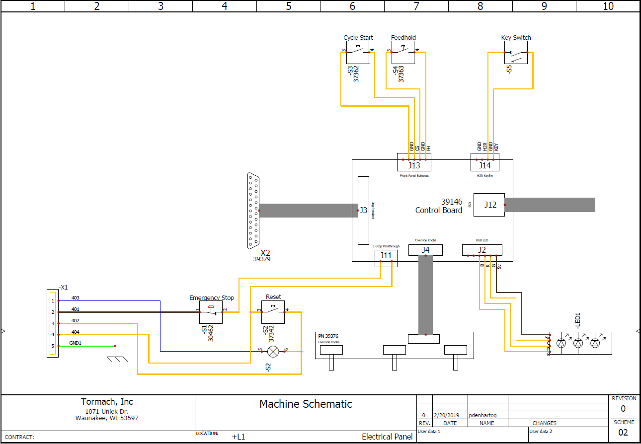
To view a PDF version of your manual, go to Tormach document TD10787.
If you have additional questions, we can help. Create a support ticket with Tormach Technical Support at tormach.com/how-to-submit-a-support-ticket for guidance on how to proceed.