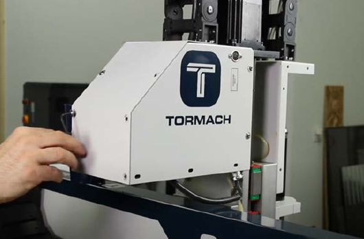
Purpose
This document gives instructions on installing the automatic tool changer on a 24R router.
Product Information
Product: Automatic Tool Changer for 24R
|
Quantity |
Description |
|
1 |
24R ATC Rack Assembly, ISO 20 (PN 38336) |
|
1 |
24R ATC Solenoid Control Panel Assembly (PN 50660) |
|
1 |
24R Filter-Regulator-Lubricator (FRL) Kit (PN 51774) |
|
1 |
|
|
2 |
|
|
2 |
ISO20 Tool Holder, ER20A, 30 mm (PN 50891) |
|
1 |
ISO20 Tool Holder Wrench (PN 50892) |
|
1 |
Lifting Dust Shoe Assembly, 80 mm, 24R ATC Compatible (PN 39088) |
|
1 |
1.5 kW ISO20 ATC Spindle Assembly (PN 51171) |
NOTE: If any items are missing, we can help. Create a support ticket with Tormach Technical Support at tormach.com/how-to-submit-a-support-ticket for guidance on how to proceed.
Air Requirements
You must verify that the site conforms to the following air supply requirements.
-
Air Pressure 90-120 psi (620-825 kPa)
If the air supply is more than 120 psi (825 kPa), you must use a regulator. -
Dry Air We recommend using a compressed air dryer, desiccator, or filter between the air compressor and the machine.
Required Tools
This procedure requires the following tools. Collect them before you begin.
-
An assistant to help you
-
3 mm hex wrench
-
4 mm hex wrench
-
6 mm hex wrench
-
14 mm wrench
-
16 mm wrench
-
Flat-blade screwdriver, small
-
Marker
-
Phillips screwdriver
-
Wood block
Before You Begin
Installation Procedure
Some machines require you to install additional components before beginning the installation procedure for the automatic tool changer (ATC).
-
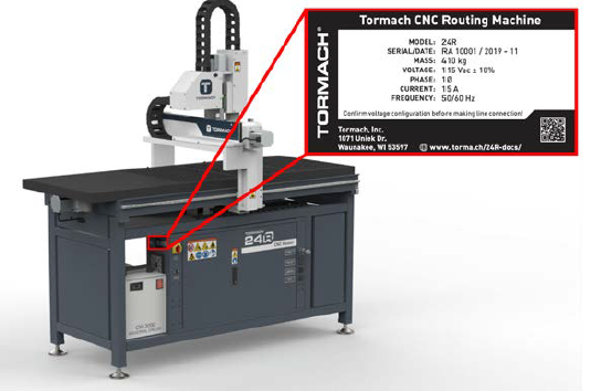
Find your machine's serial number plate on the side of the electrical cabinet.
-
Use the following table to determine which additional components to install first, depending on your specific machine. If your machine's serial number isn't listed in the table, you're ready to start the installation procedure for the ATC.
|
Serial Number |
Go to... |
|
RA10001 through RA10084 |
Install the: |
|
RA10085 through RA10096 |
Install the 24R Z-Axis Brake Retrofit Kit (PN 51136). |
Go to tormach.com/docs to find the installation instructions for these products.
Update PathPilot
If you haven't yet done so, you must update your controller to at least version 2.9.0 of PathPilot.
-
Confirm that the PathPilot controller is powered on and out of Reset mode.
-
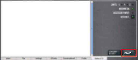
Downloading and installing an update file requires an Internet connection. From the Status tab, confirm that the Internet button LED light is on. (To configure the network, select the LED light.) Then, select Update.
-
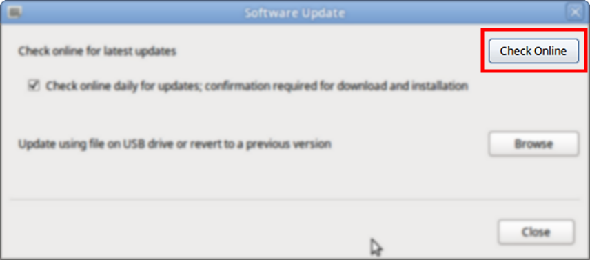
From the Software Update dialog box, select Check Online.
-
Select Install.
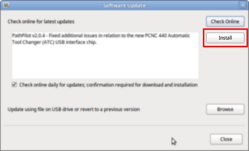
The update file is downloaded, and a notification dialog box displays.
-
From the dialog box, select OK.
The update file is installed on the PathPilot controller. -
Follow the on-screen instructions to restart the PathPilot controller.
Installation
Complete the following steps in the order listed:
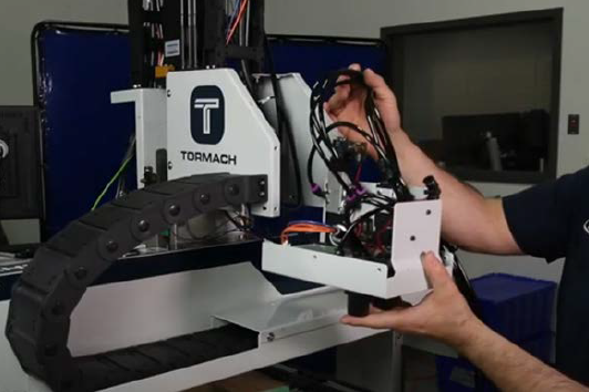
Remove the Existing Spindle (ER20)
-
Verify that the collet nut is installed and that there's no tooling in it.
-
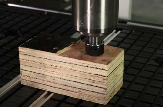
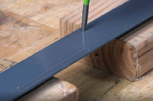
Put a block of wood below the spindle on the machine table. Then, slowly jog the Z-axis down until the spindle is resting on the block of wood.
-
Power off the machine and the PathPilot controller.
-
Push in the machine's red Emergency Stop button, which removes power to motion control.
-
From the PathPilot interface, select Exit.
-
Turn the Main Disconnect switch to OFF on the side of the electrical cabinet.
-
Follow correct lockout/tagout procedures.
-
-
Remove the six M5 button head cap screws that secure the front spindle cover with a 3 mm hex wrench. Set aside the screws and the cover.
-
Identify the spindle power connector and disconnect it.
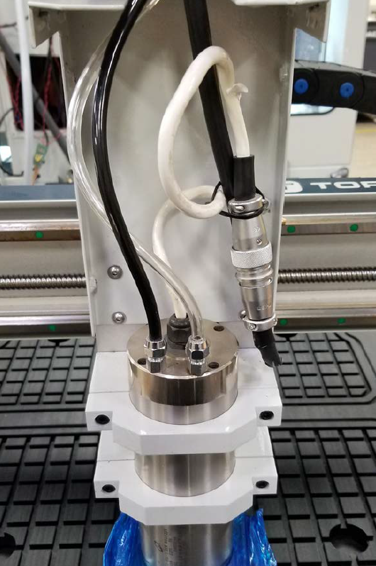
-
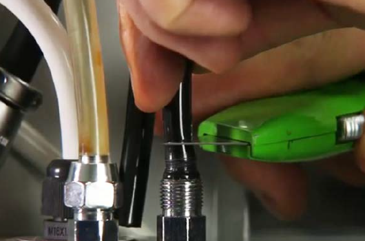
From the top of the spindle, disconnect the two water lines with a 14 mm wrench.
NOTE: We recommend that you put a piece of tape or a black mark on the clear water line. There's another clear line involved in this procedure, so marking this line helps to prevent confusion.
-
If the water lines are difficult to remove from the fitting, cut them with a knife about 1/2 in. above the fitting.
-
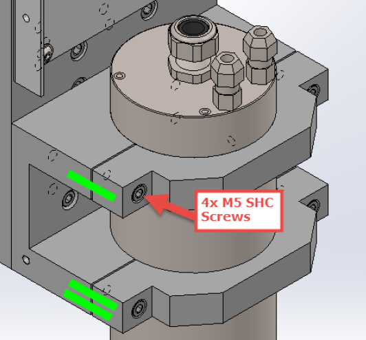
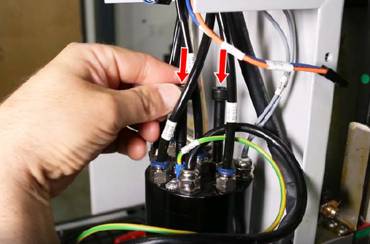
Mark each of the spindle clamps, as shown in the following image, to indicate which is the top and which is the bottom. You'll use the marks later to correctly realign the spindle clamps to the spindle mount.
-
Use one hand to support the spindle, and use your other hand to remove the four M5 socket head cap screws that secure the spindle clamps. Set aside the screws and the spindle clamps.
-
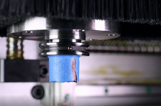
Remove the existing spindle (ER20) from the spindle mount.
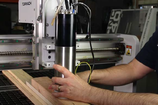
Install the New Spindle (ISO20)
Before You Begin: A Note About Spindle Heights
You can adjust the installation height on the 24R spindle to fit your project. For example, you can install it lower to be able to machine thin parts with short tools or you can raise the spindle up to give yourself more clearance for thicker parts and long tooling.
As a good starting point, we recommending starting low and keeping the black portion of the spindle flush or slightly above the top clamp.
-
Put the ISO20 spindle onto wood blocks on the machine table, and then put the spindle into the spindle mount. Orient the spindle so that the coolant ports are pointing toward the front.
-
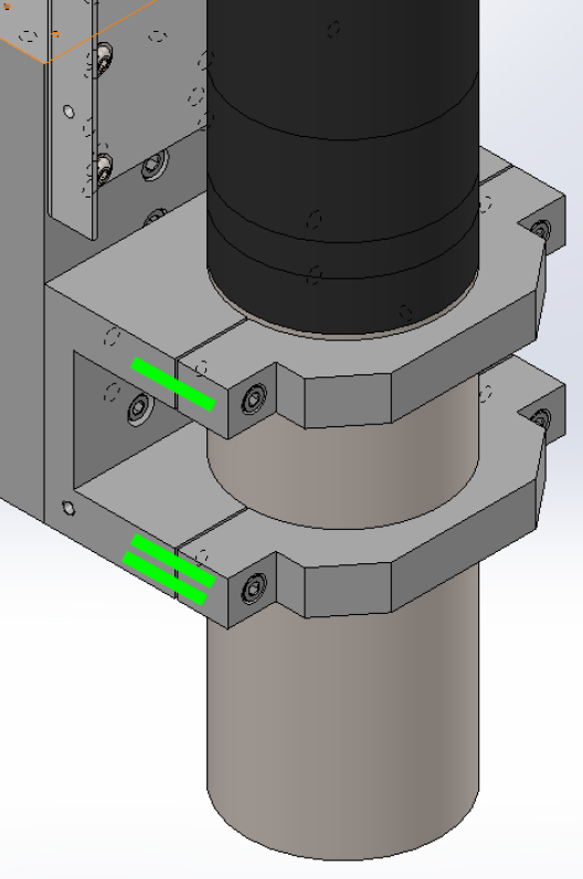
If necessary, use additional pieces of wood or cardboard to raise the spindle higher in the spindle mount. Don't mount the spindle too low — verify that both clamps are clamped on the main body (the silver section) of the spindle, and that the clamps are spaced evenly on each side.
-
Mount the ISO20 spindle with the spindle clamps and screws (that you set aside earlier) and a 4 mm hex wrench. Align the top and bottom mounts, as shown in the following image, using the marks that you made on the spindle mount before you removed the clamps.
Tip! It may be useful to have an assistant help support the spindle while you're installing the clamps.
-
Remove the two shipping bolts from the top of the spindle.
-
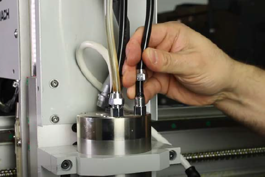
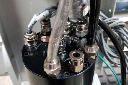
Remove the cap from the coolant ports with a 14 mm wrench. Then connect the water lines to the fittings on the top of the spindle in the following order:
-
Connect the black line to the Water Inlet.
-
Connect the clear line to the Water Outlet.
-
Identify the spindle power connector on the spindle, and connect it to the machine's spindle power connector.
-
Remove some pieces from the energy chain by gently prying them with a small, flat-blade screwdriver.
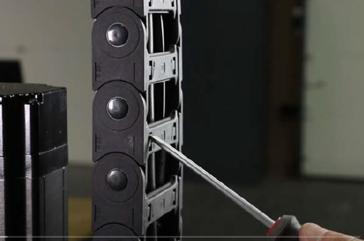
Tip! We recommend leaving a few of the energy chain pieces installed to help keep the wires and tubes organized while you route the new lines.
-
Remove the eight M5 screws that secure the rear Z-axis access panel with a 3 mm hex wrench. Set aside the screws and the panel.
-
Find the bag of hardware and wires that's provided with this kit. Then, identify the following items:
-
Power drawbar sensor cable (PDB), which contains wires 545-547.
-
Tool position sensor cable (TPS), which contains wires 548-550.
-
Connect the PDB and TPS cables to the coordinating cables on the spindle.
-
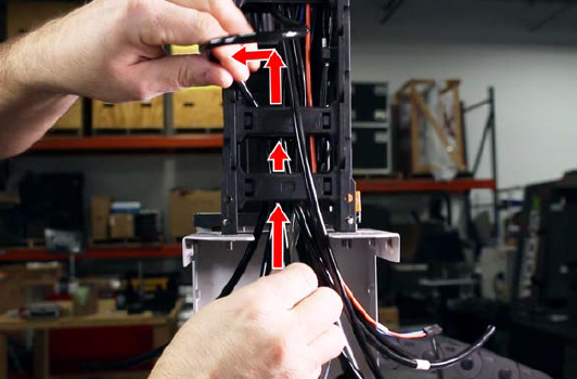
Route the following wires from through the energy chain and toward the rear Z-axis cover:
-
Power drawbar and tool position wires
-
Power drawbar open button wire
Rewire the ATC Cable
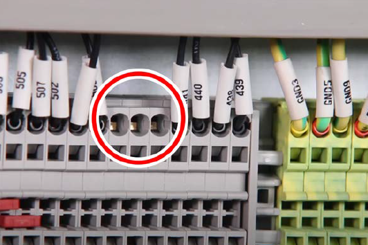
IMPORTANT! On earlier machines, the ATC cable wasn't installed on the inside of the electrical cabinet. Follow this procedure to verify this connection before installing the solenoid tray.
-
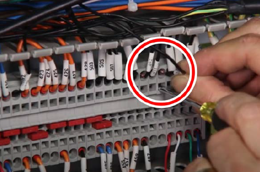
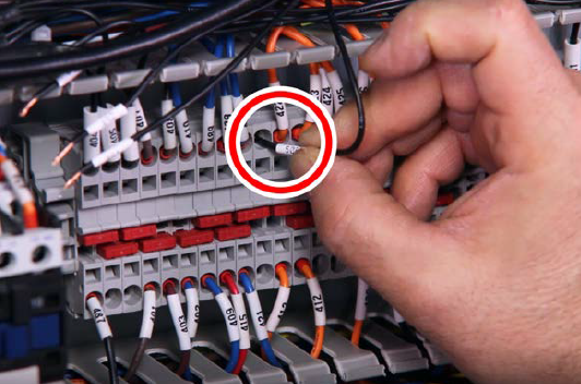
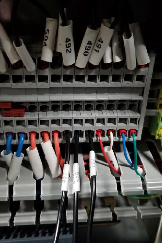
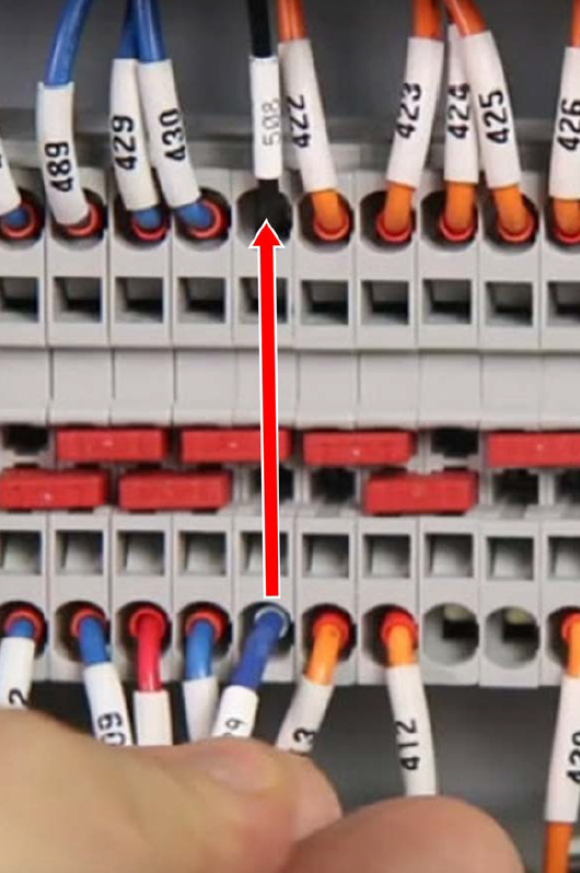
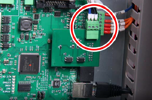
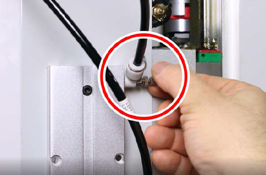
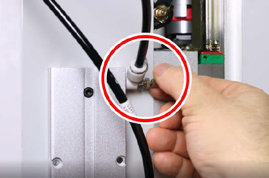
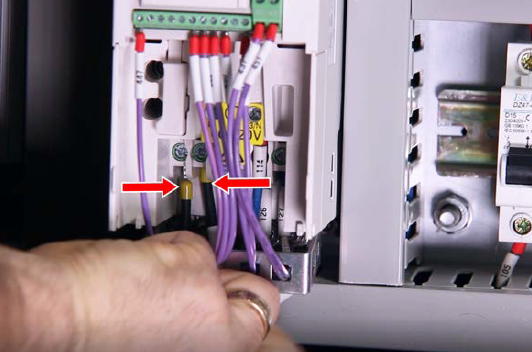
To determine if you need to connect your ATC cable, open the electrical cabinet and, on the terminal strip, find wires 490, 491, and 492.
-
If the wires are connected, as shown in the following image, skip this section and go to "Install the Solenoid Tray".
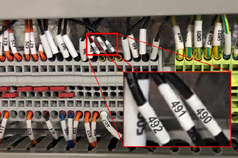
-
If the wires aren't connected, as shown in the following image, proceed to the next step in this section.
-
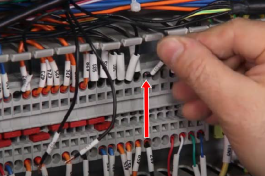
Remove the wire trough covers and set them aside.
-
In the electrical cabinet, locate the ATC cable — it's a black cable with six black wires and one green/yellow wire. The cable is in one of two places:
-
The left-most wire trough
-
The bottom wire trough
-
From the end of the ATC cable, measure 6 in. (15 cm) and make a mark.
-
Carefully strip away and remove the cable's main insulation all the way back to the mark with a knife or an insulation stripping tool.
-
Push the metal sleeve back so that it bunches up at the bottom, and carefully cut away at the material with wire cutters.
-
Trim away the extra plastic and paper from inside of the cable, and clean any talcum powder from the wires.
-
Strip 1/4 in. (6 mm) from the ends of the six black wires with a wire stripper.
-
In the rear Z-axis cover, find the round ATC connector on the ATC cable.
-
Use a multimeter to perform a continuity test between each pin on the ATC connector and each of the six black wires at the other end of the cable inside the electrical cabinet. Use the following table to identify each wire, and then apply a wire number label 2 in. from the end of each wire.
|
ATC Connector Pin |
ATC Cable Wire |
|
Pin 1 |
Wire 492 |
|
Pin 2 |
Wire 490 |
|
Pin 3 |
Wire 491 |
|
Pin 4 |
Wire 508 |
-
Trim the remaining three black wires and one green/yellow wire back to the main insulation with a pair of cutters. Because these wires aren't used for any connections, you can clean up any remaining metal sheathing and tape the wires back with electrical tape.
-
On the terminal strip, find the three open terminal blocks that you identified earlier.
-
Connect wire 492 to the terminal block by inserting it into the open part of the terminal block across from wire 487.
-
Connect wire 490 and wire 491 into the open ports on the terminal block next to wire 492.
-
Connect wire 508 to -24 Vdc by connecting it to one of the open terminals as shown below.
Install the Solenoid Tray
-
Route the extra length of air supply line back through the energy chain and to the solenoid tray.
-
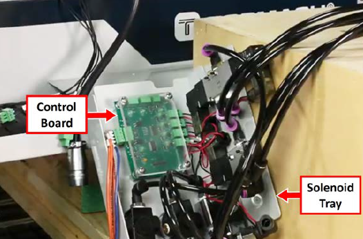
Find the solenoid tray provided with this kit, and then identify the ATC control board mounted in it.
-
Make the connections to the ATC control board as detailed in the following table.
|
Identify the... |
Connect to... |
|
BTN power drawbar button wires (from the Z-axis energy chain) |
J6 connector |
|
TPS wire cable (from the spindle) |
J7 connector |
|
PDB wire cable (from the spindle) |
J8 connector |
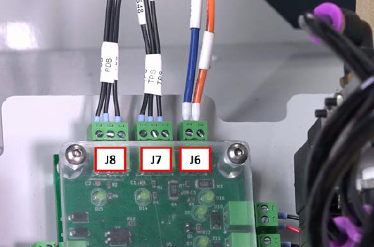
-
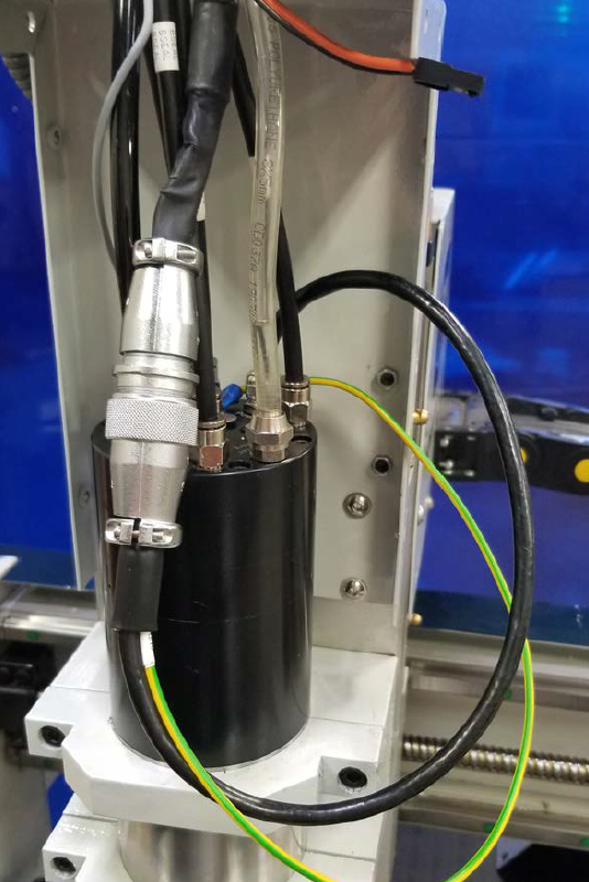
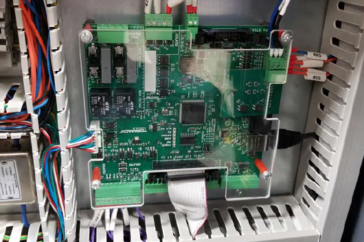
Identify the pre-installed ATC cable in the rear Z-axis cover. Then, connect it to the ATC power connector on the ATC solenoid control assembly.
-
Lift the ATC solenoid control assembly up into the bottom of the rear Z-axis cover. Align the threaded holes on the side of the tray with the horizontal slots in the rear Z-axis cover.
NOTE: Be careful to not pinch wires while lifting the tray into position.
-
Find five M5 screws provided with this kit, and use them to secure the solenoid control assembly to the rear Z-axis cover.
-
Identify the pre-installed 8 mm air hose in the rear Z-axis cover. Then, trim the length and connect it to the 8 mm push-to-connect fitting on the ATC solenoid control assembly.
NOTE: You may need to pull the air line back from within the inside of the Z-axis energy chain.
-
Reinstall all of the energy chain links that you removed earlier in this procedure.
Connect the Filter-Regulator-Lubricator (FRL) to the Rear of the Machine
-
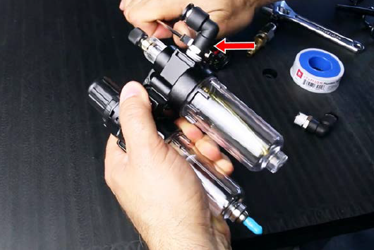
Remove the two 1/4 in. push-to-connect fittings on either side of the FRL with a 14 mm open socket wrench.
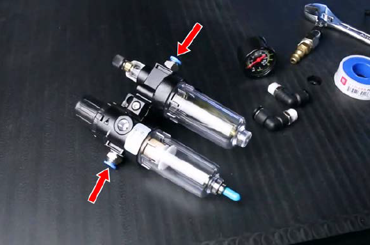
-
Install the two included 5/16 in. push-to-connect elbows to either side of the FRL with a 14 mm open socket wrench. Teflon tape is preinstalled on these elbows.
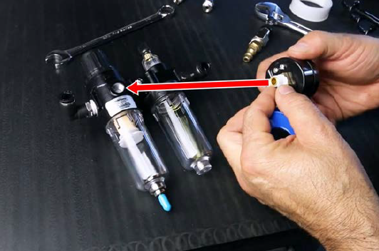
-
Wrap Teflon tape onto the threads of the included dial. Then, install the dial on the FRL. Do not overtighten.
-
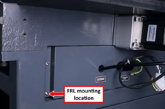
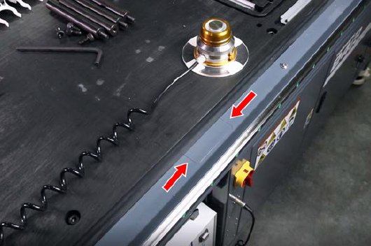
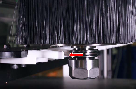
On the rear of the machine, remove the bottom hex screw on the panel shown in the following image with a hex wrench.
-
Slide the included socket head cap screw into the top FRL bracket, and slide the spacer onto the backside of the screw. Then, secure the socket head cap screw to the machine with a 3 mm hex wrench.
-
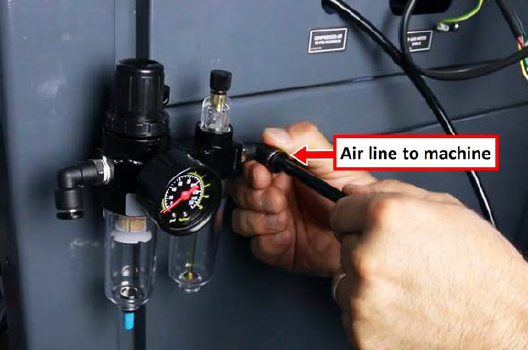
Attach the air line going into the machine to the right push-to-connect elbow on the FRL.
-
Connect the loose end of the 6 in. air line (with the air fitting) to the left push-to-connect elbow on the FRL.
IMPORTANT! Don't connect the fitting to your shop's air supply yet. You'll do so later in this procedure.
Connect the Air Lines to the Spindle
-
Route the loose ends of the air lines from the solenoid panel assembly, through the Z-axis energy chain, and toward the spindle.
-
Identify the two air lines labeled Lift and EXT. Route the air lines toward the spindle and out the front of the Z-axis energy chain two links before the spindle cover. You'll connect the air lines later in this procedure.
-
Identify and connect the following air lines to the push-to-connect fittings on the top of the spindle.
|
Air Line |
Fitting |
|
Blast |
Dust Removal |
|
Open |
Air Inlet |
|
Seal |
Air Sealed |
|
Close |
Air Return |
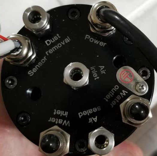
Tip! If the air lines are too long, trim them to length.
Install the Power Drawbar Button
-
Unplug the power drawbar button at the connector near the spindle from the wires previously routed up through the Z-axis energy chain.
-
Put the power drawbar button into the hole on the spindle cover, and tighten the lock washer and nut onto the button.
NOTE: Earlier machines (RA10001-RA10036) didn't include a hole for the power drawbar button. If you have one of these machines, use the new Spindle Cover (PN 39086) provided in this kit.
-
While holding the spindle cover up to the spindle head, identify the power drawbar button wires from the Z-axis energy chain, and plug them in to the power drawbar button.
-
Attach the spindle cover to the spindle head with the six M5 screws from earlier in this procedure and a 3 mm hex wrench.
Install the Lifting Dust Shoe
-
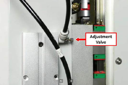
Verify that the top push-to-connect fitting on the dust shoe has the adjustment valve. If it's installed on the bottom, remove it with a wrench and switch it to the top location. Securely tighten both fittings.
-
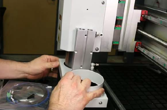
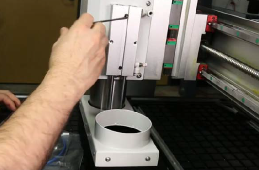
Slide the non-flanged end of the dust shoe onto the spindle. Then, align the center dust shoe holes on the spindle cover.
-
Mount the dust shoe to the spindle cover with the two socket head cap screws and a 3 mm hex wrench.
-
Install the air line labeled LIFT to the push-to-connect fitting into the lower port on the double rod cylinder (nearest to the dust shoe).
-
Install the air line labeled EXT to the push-to-connect fitting into the upper port on the double rod cylinder (furthest from the dust shoe).
-
Lift and lower the dust shoe, and observe the motion to determine if it rubs on the spindle. If it does, loosen the Phillips head screws a quarter-turn to adjust the position of the shoe until it's clear of the spindle. Then, re-tighten the Phillips head screws.
Install the ATC Communication Board
-
In the electrical cabinet, from the machine control board, remove the four screws securing the acrylic board shield with a 2.5 mm hex wrench. Set aside the shield and the screws.
-
Find the ATC communication board provided in this kit. Then, plug the black connector on the ATC communication board into the P1 auxiliary port on the machine control board.
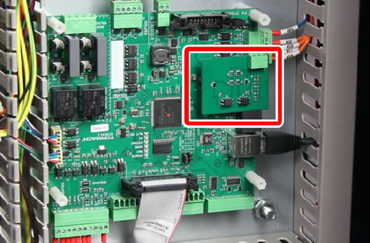
Locate the wire harness for the ATC communication board with wires labeled 530 and 531. Connect them as follows:
-
Connect the loose end of wire 530 to the open port of the terminal block connected to wire 490.
-
Connect the loose end of wire 531 to the open port of the terminal block connected to wire 491.
-
Connect the loose end of wire 529 to the open port of the terminal block connected to wire 508.
-
Plug the green connector of the wire harness into the J2 connector on the ATC communication board.
-
Re-install the acrylic board shield to the machine control board with the four screws that you set aside earlier.
NOTE: If the spacers used previously no longer work, we've included additional plastic spacers in this kit for you to use.
-
Tuck all of the wires back into the wire troughs and replace all of the wire trough covers.
Install the ATC Rack
Prepare the Machine
-
On the machine table, near the back end (Y+) of the machine, locate the three M8 threaded holes on each side of the machine. You'll use these to mount the ATC rack. If you don’t see the three threaded holes, you must remove the linear rail cover punch-outs.
Remove Linear Rail Cover Punch-Outs
NOTE: If your machine has punch-outs on the linear rail covers, you must remove them before you mount the ATC rack.
-
Remove the five M5 button head cap screws securing the left and right linear rail covers to the bed casting with a 3 mm hex wrench.
-
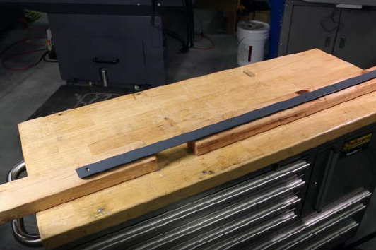
Put a short and a long wood block onto a secure work surface and align the first linear rail cover in the open space.
-
Support one of the linear covers with two wooden blocks, aligning the punch-out between the blocks.
-
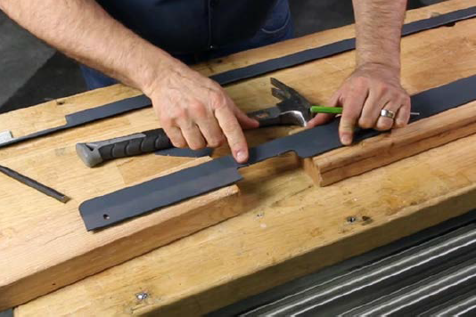
Break the tabs securing the punch-out to the linear rail cover with a punch and a hammer. Start with one of the tabs closest to the edge of the linear rail cover.
-
Break the remaining tabs one-by-one, working your way around the punch-out until all of the tabs are broken. Remove the punch-out.
-
Repeat Steps 2 through 4 with the punch-out on the other linear rail cover.
-
Re-attach the linear rail covers to the bed of the machine with a 3 mm hex wrench and the five M5 button head cap screws that you set aside in Step 1.
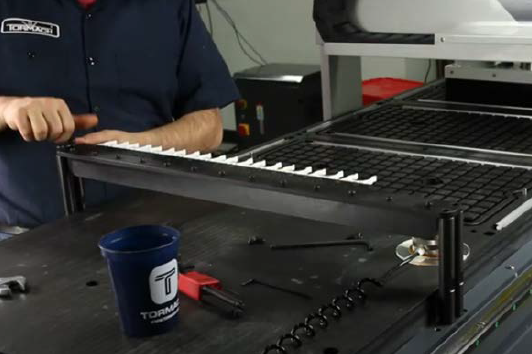
Mount the ATC Rack
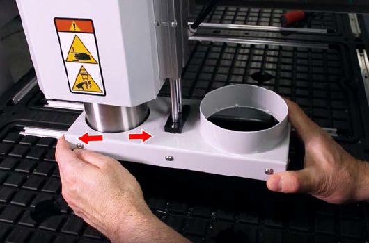
-
Find the ATC rack provided with this kit. Then, remove the four M8 bolts securing the standoffs to the bottom of the ATC rack with a 6 mm hex wrench and a 16 mm wrench. Set aside the M8 bolts.
-
Identify the two sets of three holes on either side of the machine table. You'll install the ATC rack's two standoffs into two of the holes (the hole that's furthest to the left is unused and remains open).
-
Install the standoffs into the two holes with a 16 mm wrench.
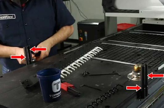
-
Turn the rack so that the mounting screws for the tool forks are on the bottom of the rack, and then mount the ATC rack to the top of the standoffs with the four M8 bolts that you set aside earlier.
Adjustments and Verification
After installing all of the components of the ATC, you must make adjustments and do testing to verify that the ATC was properly installed. Complete the steps in the following sections before using the ATC.
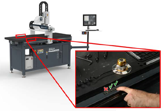
Inspect the ATC Control Board
-
Power on the machine and the PathPilot controller.
-
Insert the power plug(s) into the wall outlet. If your system is hardwired, restore power to the circuit breaker(s).
-
Turn the Main Disconnect switch to ON on the side of the electrical cabinet.
-
Twist out the machine's red Emergency Stop button, which enables movement to the machine axes and the spindle.
-
Press the Reset button.
-
Bring the machine out of reset and reference it.
-
-
If you haven't yet done so, you must update your controller to at least version 2.9.0 of PathPilot. From the PathPilot interface, on the Status tab, select Update.
-
Once PathPilot has been updated, from the Settings tab, select Rack Tool Changer.
The Rack ATC tab displays next to the Status tab. -
In the rear Z-axis cover, on the ATC control board, inspect the Power and Status LED lights. Confirm that they're illuminated as detailed in the following table.
|
LED |
Light |
|
Power (green) |
On |
|
Status (amber) |
Off |
Adjust the ATC Air Pressure Settings
The ATC has three air pressure control settings that you must adjust before operation.
Pressure Control Settings Overview
The three air pressure control settings are:
-
Spindle Nose Seal and Dust Shoe Extend Pressure Regulator (closest to the operator side of the machine (X-))
-
Dust Shoe Lift Pressure Regulator (furthest from the operator side of the machine)
The Spindle Nose Seal and Dust Shoe Extend Pressure Regulator has two functions:
-
The ISO20 spindle has a positive pressure air seal around the spindle nose. The constant flow of air from the spindle nose keeps dust out of the spindle bearings during operation. The pressure regulator controls the flow rate of air that is purged from the spindle nose.
-
This pressure regulator also adjusts the downward force applied to the lifting dust shoe.
Both the spindle nose air seal and the downward force on the lifting dust shoe require the same amount of air pressure. The downward force on the lifting dust shoe should be enough to fully extend the dust shoe but not enough to fold the bristles in half when lifting the dust shoe with both hands.
The Dust Shoe Lift Pressure Regulator controls the upward force applied to the lifting dust shoe when in the up position. The pressure should be set such that the dust shoe fully lifts when commanded and the dust shoe can still be pushed downward with two fingers.
The Dust Shoe Lift Pressure Regulator should be adjusted after adjusting the Spindle Nose Seal and Dust Shoe Extend Pressure regulator.
The Dust Shoe Lift Speed Control Valve fitting is a one way flow control valve and it controls how quickly the dust shoe moves upward when it is lifted. This valve should be open when adjusting the Spindle Nose Air Seal and Dust Shoe Extend Pressure Regulator and then fine tuned after setting the pressure on the Dust Shoe Lift Pressure Regulator.
Adjust the Spindle Nose Air Seal and Dust Shoe Extend Pressure Regulator
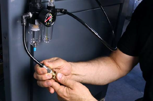
-
At the back of the machine, connect the air line from the air compressor to the FRL's air fitting inlet that you connected earlier. Verify that the air compressor is set between 90 psi and 120 psi.
-
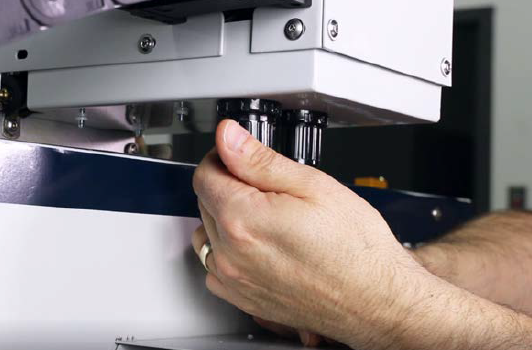
Identify the dust shoe lift speed control valve on the top of the lifting dust shoe cylinder. Loosen the locking nut. Then open the valve by turning the adjustment screw counterclockwise 1-3 full turns.
-
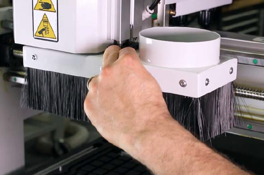
On the bottom of the ATC solenoid control panel, identify the spindle nose air seal and dust shoe extend pressure regulator, and pull down to unlock the pressure regulator.
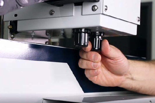
-
Turn the knob clockwise to increase the air pressure until you begin to hear air coming from the air seal around the nose of the spindle.
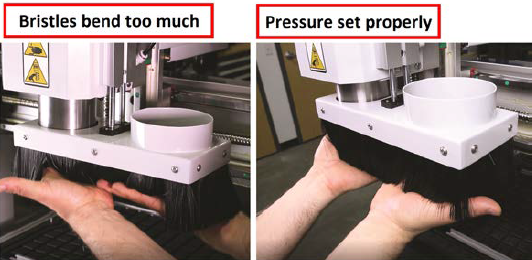
-
Place the palms of both hands below the bristles of the lifting dust shoe and lift the dust shoe upward. Then release the lifting dust shoe and allow it to extend.
-
If the lifting dust shoe does not fully extend, turn the air pressure regulator clockwise to increase the pressure.
-
If the bristles on the dust shoe bend too much when lifting the dust shoe with both hands, turn the pressure regulator counterclockwise to decrease the pressure.
-
-
Once the pressure is set properly, push the knob back up to lock the pressure regulator.
Adjust the Dust Shoe Lift Pressure Regulator
-
From the PathPilot interface, select Lift/Lower Dust Shoe.

-
On the bottom of the ATC solenoid control panel, identify the dust shoe lift pressure regulator, and pull down to unlock the pressure regulator.
-
Turn the knob clockwise to increase the lifting pressure until the dust shoe lifts all the way up.
-
Using two fingers, push the lifting dust shoe downward.
-
If you can't push the lifting dust shoe downward with two fingers, turn the pressure regulator counterclockwise to decrease the pressure.
-
From the PathPilot interface, select Lift/Lower Dust Shoe. The dust shoe goes back down.
Adjust the Dust Shoe Lift Speed Control Valve
-
From the PathPilot interface, select Lift/Lower Dust Shoe to lift the dust shoe. Observe the speed of how quickly the dust shoe lifts.
-
Select Lift/Lower Dust Shoe Button to lower the dust shoe.
-
On the top of the dust shoe lifting cylinder, identify the dust shoe lift speed control valve.
-
Adjust the dust shoe lifting speed as follows:
-
Rotate the adjustment screw clockwise to decrease the speed.
-
Rotate the adjustment screw counterclockwise to increase the speed.
-
-
Repeat Steps 1 through 4 until the dust shoe lifts and lowers at roughly the same speed.
Verify the Power Drawbar Function
-
Identify the PDB button on the front of the spindle cover, and press and hold the power drawbar button.
The power drawbar valve opens, and the power drawbar opens inside of the spindle. -
Insert an ISO20 tool holder into the spindle and release the power drawbar button.
The drawbar closes and locks the tool into the spindle.
NOTE: The power drawbar button does not lock the PDB in the open position. The PDB closes when the button is released. -
While holding the tool in the spindle, select the Collet button on the Rack ATC tab in the PathPilot interface.
The drawbar opens, releasing the tool from the spindle, and remains in the open position.
NOTE: The collet button in PathPilot opens the power drawbar and locks it in the open position until either the collet button is pressed again or the PDB button on the front of the spindle is pressed and released. -
Remove the tool from the spindle. Then, select Collet.
The drawbar closes. -
Select Collet to lock the drawbar in the open position. Then, select Air Blast.
Air purges from the center of the spindle until you press the button again.
Select Air Blast again to turn the blast off.
NOTE: The Air Blast button is used to test the air blast from the center of the spindle. The air blast is used to clear chips, dust and debris from the tool shanks when the machine performs an Automatic Tool Change.
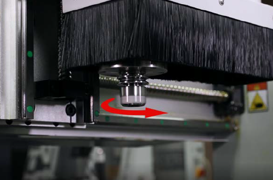
Verify the Spindle Direction
NOTICE! You must verify the spindle direction before operating the machine. If you don't, you could operate the spindle in the reverse direction, which could damage the spindle.
-
Remove the collet nut from an ISO20 tool holder and put a piece of tape onto the side of the tool holder. Draw a vertical line onto the tape. Then install the tool holder into the spindle.
-
From the PathPilot interface, on the Main tab, in the RPM DRO field, type 10,000. Then select the Enter key.
-
While observing the spindle, select Fwd, and then select Stop.
The spindle turns on, rotates counterclockwise, and turns off.
-
Depending on the direction in which the spindle rotated in Step 3, do one of the following:
-
Rotates Clockwise (Viewed from Above) You've completed the spindle function verification. Go to "Align the ATC Rack".
-
Rotates Counterclockwise (Viewed from Above) Power off the machine and, on the variable frequency drive (VFD), swap wire U and wire V. Then, power on the machine, and repeat Steps 2 through 3.
Align the ATC Rack
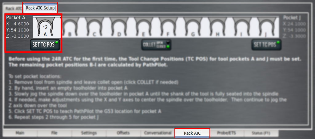
Before using the 24R ATC for the first time, you must set the tool change positions for tool pockets A and J to align the ATC rack to the machine's reference position.
-
Install an ISO20 holder into the spindle.
-
Jog the machine in front of the left-most pocket (Pocket A) of the ATC rack.
-
Jog the spindle down to visually align the ATC fork with the tools holder's groove.
-
Jog the machine in the Y+ direction to move the tool holder into the ATC rack while watching the tool fork. You want to see both forks start to bend out at the same time when the tool starts engaging the fork. Make any adjustments needed in the X direction.
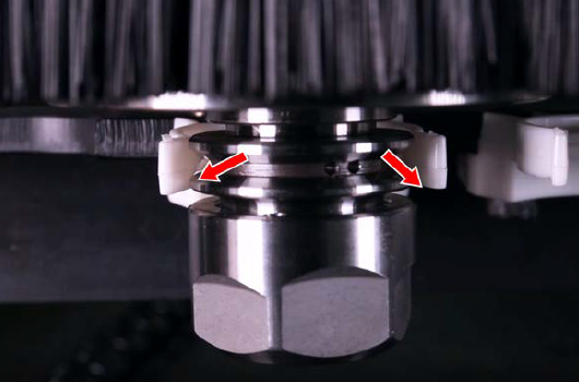
-
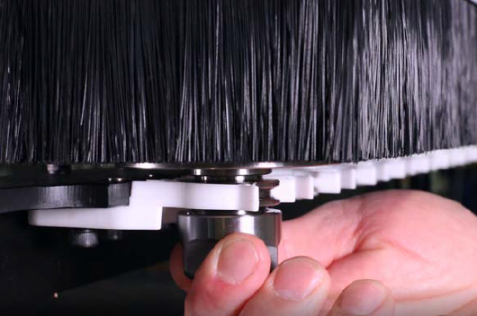
Continue jogging the machine in the Y+ direction until the holder is seated in the ATC fork. You can determine this visually or by rotating the tool by hand. When the tool holder touches the back of the fork, you'll feel the drag increase.
-
From the PathPilot interface, select Set TC POS below pocket A to teach the location for Pocket A.
-
Jog the machine in the Y- direction to remove the tool from the ATC rack.
NOTE: Keep the Z height at the same position to help reduce the setup time for Pocket J.
-
Jog the machine over to the right-most pocket (Pocket J), and repeat Steps 3-5.
-
From the PathPilot interface, Set TC POS below pocket J to teach the location for Pocket J.
-
Jog the machine in the Y- direction to remove the tool from the ATC rack.
-
You can make fine adjustments by directly editing the TC positions on the Rack ATC Setup tab. It's important to note that what's displayed are the G53 or machine coordinates. To have your machine's DRO match these values, you must:
-
Have a work coordinate active with all values set to 0, and
-
Have T0 active or a tool with a 0 in. offset.
Run the Spindle Break-In Program
To prolong bearing life and reduce spindle noise, it's important to run the spindle through a break-in procedure before operating the machine. Complete the following steps to run the spindle through a break-in cycle. You only must perform this procedure once for a new spindle.
NOTE: The total cycle time for the spindle break-in procedure is 195 minutes.
-
If you haven't yet done so, you must first install the spindle chiller before running this break-in program. For information, see the operator's manual.
-
Load a tool into the spindle. You can use an empty tool holder for this procedure.
-
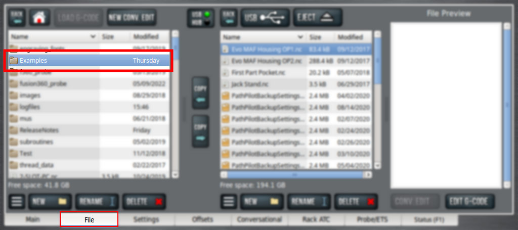
From the PathPilot interface, on the File tab, open the Examples folder. Then, double click the program called 24R_spindle_breakin.ngc.
The program loads on the Main tab.
-
Select Cycle Start.
The spindle runs through the three-hour break-in procedure, where it rotates in increments of 10,000, 20,000, and 24,000 rpm. After the program finishes, the break-in procedure is complete.
Operation
Read the following sections to understand how to operate the ATC:
Load a Tool into the Spindle
-
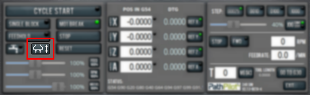
From the PathPilot interface, select Dust Shoe.
The dust shoe lifts.

-
With one hand, press and hold the power drawbar button on the front of the spindle cover.
The drawbar opens. -
With the other hand, insert the shank of the tool into the spindle taper.
-
While holding the tool into the spindle taper, release the power drawbar button.
The drawbar closes and clamps the tool into the spindle. -
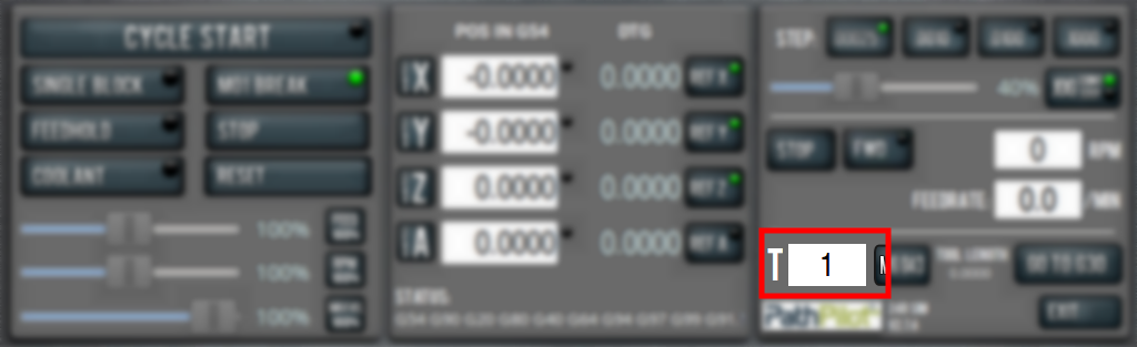
From the PathPilot interface, in the Tool Number DRO field, type the tool number. Then select the Enter key.

Remove a Tool from the Spindle
-
From the PathPilot interface, select Dust Shoe.
The dust shoe lifts.
-
With one hand, support the tool holder in the spindle.
-
With the other hand, press and hold the power drawbar button of the front of the spindle head.
The tool releases. -
From the PathPilot interface, in the Tool Number DRO field, type 0. Then select the Enter key.
Store the Current Tool into the ATC Rack
By default, the ATC is a random pocket ATC. This means that, to load and store a tool into the ATC rack, you only need to select the Store Current Tool button — PathPilot then finds an open pocket to use. However, you can also actively select a specific pocket by using the Selected Pocket drop-down menu.
Automatically Select a Pocket
-
If you haven't yet done so, load a tool into the spindle.
-
From the PathPilot interface, on the Rack ATC tab, select Store Current Tool. The Selected Pocket drop-down menu selection defaults to Auto Pocket.
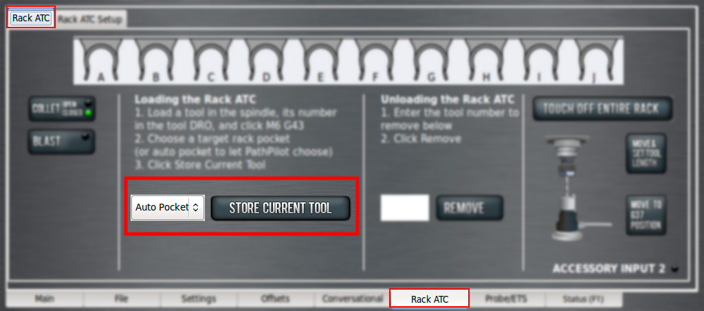
The machine moves to the first available ATC pocket and stores the tool in the ATC rack.
Select a Specific Pocket
-
If you haven't yet done so, load a tool into the spindle.
-
From the PathPilot interface, on the Rack ATC tab, select a pocket from the Target Rack Pocket drop-down menu.
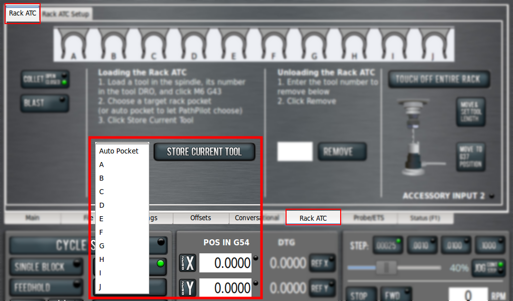
-
Select Store Current Tool.
The machine moves to the selected ATC pocket and stores the tool in the ATC rack.
Fetch a Tool from the ATC Rack
-
From the PathPilot interface, in the Tool Number DRO field, type the desired tool number. Then select the Enter key.
-
In the Use ATC to fetch tool #? dialog box, select Yes.
The spindle moves to the selected tool and loads it into the spindle.
Remove a Tool from the ATC Rack
-
From PathPilot interface, on the Rack ATC tab, in the Remove DRO field, type the tool number. Then select the Enter key.
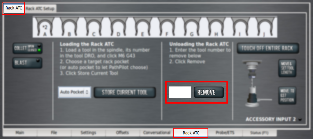
-
Select Remove.
The machine fetches the selected tool from the ATC rack, deletes the tool number from the ATC, and returns to the tool loading position. -
With one hand, support the tool holder in the spindle.
-
With the other hand, press and hold the power drawbar button of the front of the spindle head.
The tool releases. -
From the PathPilot interface, in the dialog box, select OK.
The dialog box closes and PathPilot changes the current tool number in the Tool Number DRO to 0.
Measure a Tool
-
If you haven't yet done so, load a tool into the spindle.
-
From the PathPilot interface, on the ATC tab, select Move & Set Tool Length.
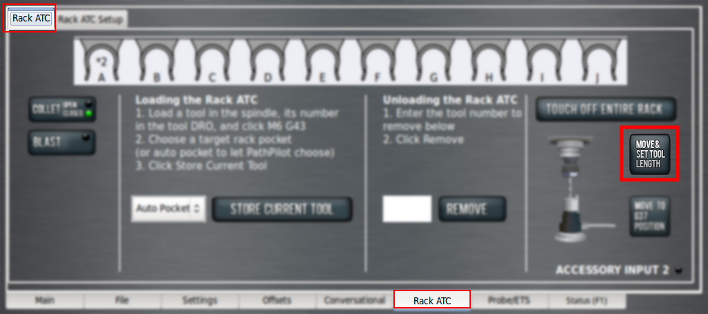
The machine moves to the tool setter, measures the tool, and applies the offsets in the Tool Table window (on the Offsets tab).
-
Store the tool into the ATC. For information, see "Store the Current Tool into the ATC Rack".
Touch Off Entire ATC Rack
Rather than loading and measuring each tool separately, you can instead use the machine and an Electronic Tool Setter (ETS) to measure all of the tools that are loaded in the ATC rack.
-
If you haven't yet done so, load all of the desired tools into the ATC rack.
-
If you haven't yet done so, set up the ETS. For information, see the operator's manual.
NOTE: Even if you've previously set up the ETS, you must repeat the procedure after installing the new ATC spindle.
-
From the PathPilot interface, on the ATC tab, select Touch Off Entire Rack.
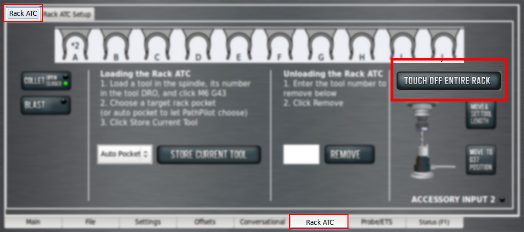
The machine fetches each tool from the ATC rack, measures the tool with the ETS, and then stores the tool back into the ATC rack. The machine repeats this process for all tools stored in the ATC rack.
Programming
Dust Shoe Control (M27 and M28)
To raise or retract the dust shoe, program: M27
To lower or extend the dust shoe, program: M28
For more information on programming, refer to your machine's operator's manual.
Automatic Tool Changer Diagrams and Parts Lists
ATC Solenoid Control Panel Assembly
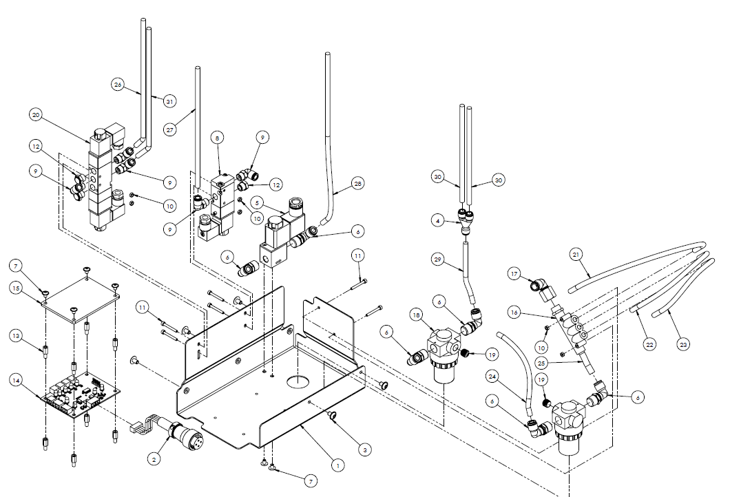
|
ID |
Description |
Quantity |
|
1 |
24R ATC Solenoid Control Panel (PN 50661) |
1 |
|
2* |
Circular Connector, Plug, PVC Jacket, 20 mm, 4-Pin Male, Solder (PN 35193) |
1 |
|
3 |
Screw, Button Head Cap, Flanged M5 × 0.8 - 8, 18-8 Stainless Steel (PN 38889) |
6 |
|
4 |
Fitting, Wye, 1/4 in. PTC (PN 38550) |
1 |
|
5 |
Two Port, Two Way, Two Position, 24 Vdc, Single Solenoid Valve, 1/4 in. (inlet/outlet), Normally Closed (PN 38827) |
1 |
|
6 |
Fitting, Elbow, 1/4 in. NPT (Male) - 1/4 in. PTC (PN 31324) |
6 |
|
7 |
Screw, Button Head Cap, Flanged M4 × 0.7 - 6, 18-8 Stainless Steel (PN 20001) |
6 |
|
8 |
Three Port, Three Way, Two Position, 24 Vdc, Single Solenoid Valve, 1/8 in. (inlet/outlet), 1/8 in. (exhaust) (PN 50647) |
1 |
|
9 |
Fitting, Elbow, 1/8 in. NPT (Male) - 1/4 in. PTC (PN 34886) |
5 |
|
10 |
Nut, Hex, M3, Zinc Plated (PN 31086) |
6 |
|
11 |
Screw, Socket Head Cap, M3 × 0.5 - 25 (PN 50768) |
6 |
|
12 |
Ftg, Muffler (Flat), 1/8 NPT (PN 37297) |
3 |
|
13 |
Standoff, 10 mm, M4 × 0.7 - 8 mm Male, M4 × 0.7 - 5 mm Female, Steel (PN 50765) |
8 |
|
14 |
PCB, 24R ATC Board (PN 50683) |
1 |
|
15 |
24R ATC Board Shield, Acrylic (PN 50766) |
1 |
|
16 |
Fitting, Male Manifold, 1/4 in. NPT - 1X 5/16 in. PTC Ports - 3X 1/4 in. PTC Ports (PN 50685) |
1 |
|
17 |
Fitting, Elbow, 1/4 in. NPT (Female) – 5/16 in. PTC (PN 50840) |
1 |
|
18 |
Pressure Regulator, 1/4 in. NPT × 1/4 in. NPT, 1/8 in. NPT Gauge Port, 7-125 PSI, 150 PSI (PN 39356) |
2 |
|
19 |
Fitting, Plug (Internal Hex), 1/8 in. NPT (Male), Brass (PN 35892) |
2 |
|
20 |
Five Port, Four Way, Three Position, 24 Vdc, Double Solenoid Valve, 1/8 in. (inlet/outlet), 1/8 in. (exhaust), Exhausted Center Position (PN 50705) |
1 |
|
21 |
Tubing, Polyethylene Air Line, 1/4 in. OD, Black, 35 cm Long (PN 31457) |
1 |
|
22 |
Tubing, Polyethylene Air Line, 1/4 in. OD, Black, 20 cm Long (PN 31457) |
1 |
|
23 |
Tubing, Polyethylene Air Line, 1/4 in. OD, Black, 14 cm Long (PN 31457) |
1 |
|
24 |
Tubing, Polyethylene Air Line, 1/4 in. OD, Black, 14 cm Long (PN 31457) |
1 |
|
25 |
Tubing, Polyethylene Air Line, 1/4 in. OD, Black, 5 cm Long (PN 31457) |
1 |
|
26 |
Tubing, Polyethylene Air Line, 1/4 in. OD, Black, 125 cm Long (PN 31457) |
1 |
|
27 |
Tubing, Polyethylene Air Line, 1/4 in. OD, Black, 140 cm Long (PN 31457) |
1 |
|
28 |
Tubing, Polyethylene Air Line, 1/4 in. OD, Black, 125 cm Long (PN 31457) |
1 |
|
29 |
Tubing, Polyethylene Air Line, 1/4 in. OD, Black, 23 cm Long (PN 31457) |
1 |
|
30 |
Tubing, Polyethylene Air Line, 1/4 in. OD, Black, 115 cm Long (PN 31457) |
2 |
|
31 |
Tubing, Polyethylene Air Line, 1/4 in. OD, Black, 125 cm Long (PN 31457) |
1 |
|
*24R ATC Cable Board Harness includes PN 35913, wires and board connector. |
||
ATC Rack Assembly
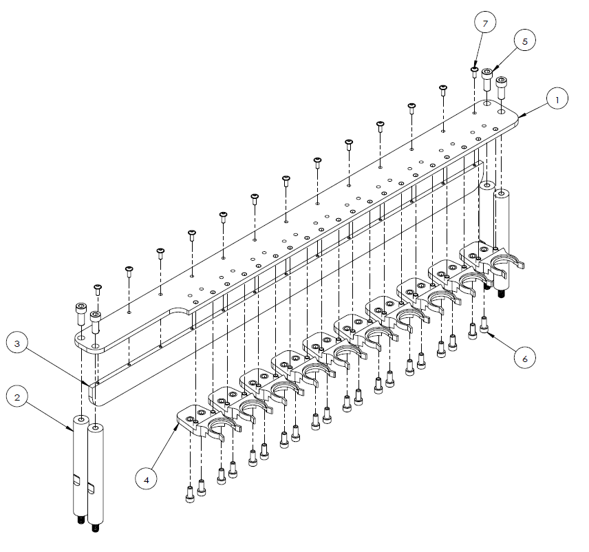
|
ID |
Description |
Quantity |
|
1 |
24R ATC Tool Holder Rack (PN 38337) |
1 |
|
2 |
24R ATC Rack Supports (PN 39724) |
4 |
|
3 |
Tool Holder Rack Reinforcement Rib (PN 50684) |
1 |
|
4 |
ISO20 Tool Holder Fork (PN 38338) |
10 |
|
5 |
Screw, Socket Head Cap, M8 × 1.25 - 20 (PN 31895) |
4 |
|
6 |
Screw, Socket Head Cap, M6 × 1 - 14 (PN 51161) |
20 |
|
7 |
Screw, Button Head Cap (Flanged), M4 × 0.7 - 12, 18-8 Stainless Steel (PN 38920) |
13 |
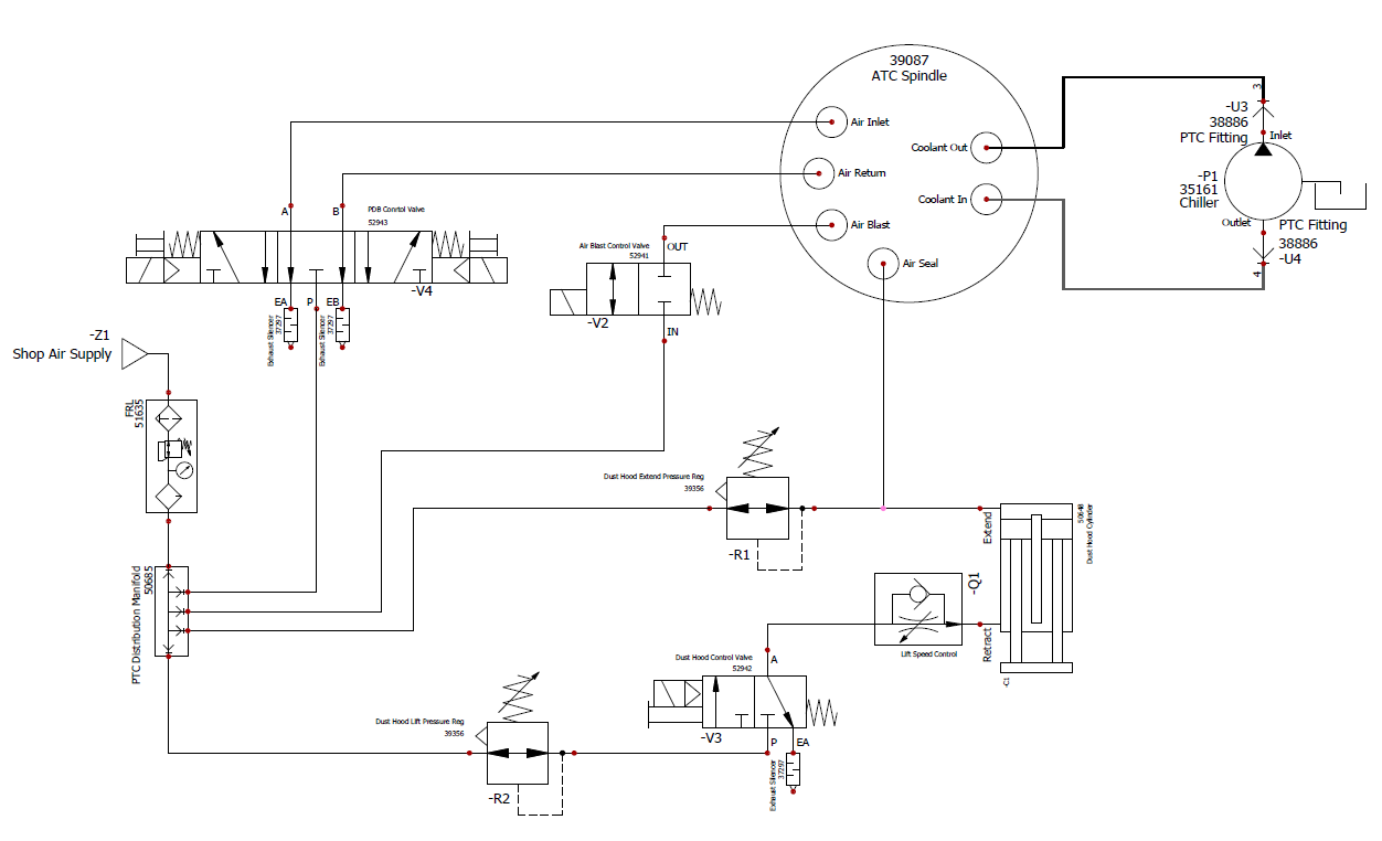
ATC Spindle Pneumatics and Waterlines
To view a PDF version of your manual, go to Tormach document TD10763.
If you have additional questions, we can help. Create a support ticket with Tormach Technical Support at tormach.com/how-to-submit-a-support-ticket for guidance on how to proceed.