Purpose
This document gives instructions on installing the 24 Vdc Power Supply for 24R Router.
Product Information
Product: 24 Vdc Power Supply for 24R Router (PN 51138)
Required Tools
This procedure requires the following tools. Collect them before you begin.
-
Flat-blade screwdriver, small
Remove the Existing Power Supply
WARNING! Electrical Shock Hazard: You must power off the machine before making any electrical connections. If you don't, there's a risk of electrocution or shock.
-
Power off the machine and the PathPilot controller.
-
Push in the machine's red Emergency Stop button, which removes power to motion control.
-
From the PathPilot interface, select Exit.
-
Turn the Main Disconnect switch to OFF on the side of the electrical cabinet.
-
Remove the power plug(s) from the wall outlet. If your system is hardwired, isolate the machine by opening its circuit breaker(s).
-
Follow correct lockout/tagout procedures.
-
-
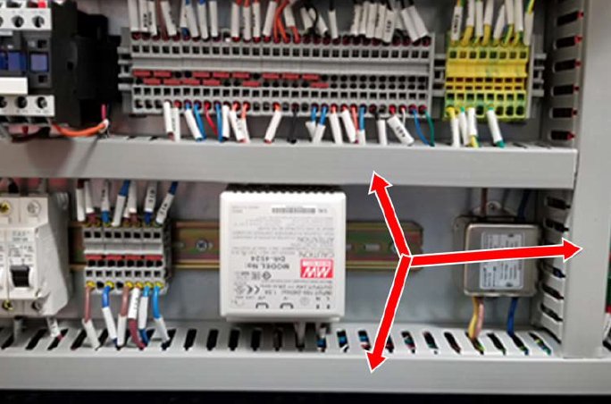
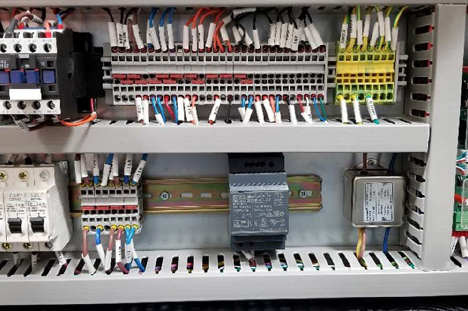
From the electrical cabinet, remove the three wire trough covers shown in the following image. Set the wire trough covers aside.
-
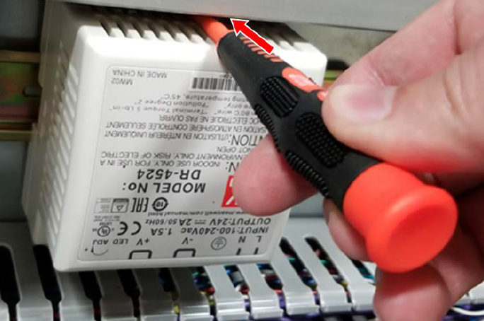
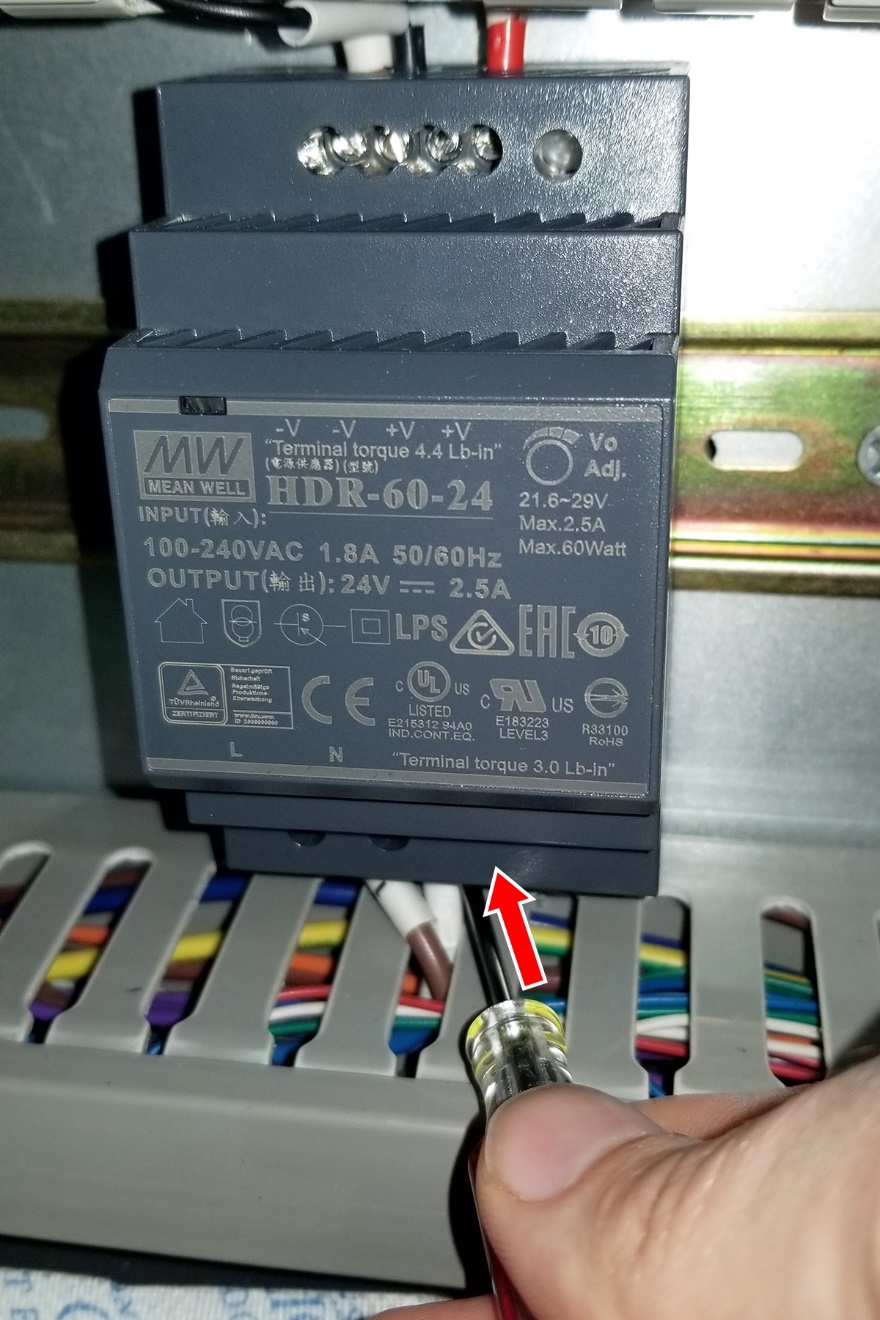
Identify the existing power supply. Depending on which machine you have, the power supply is either white or gray (as shown in the following images). Lift the DIN rail clip on the power supply with a small, flat-blade screwdriver to remove it from the electrical cabinet.
-
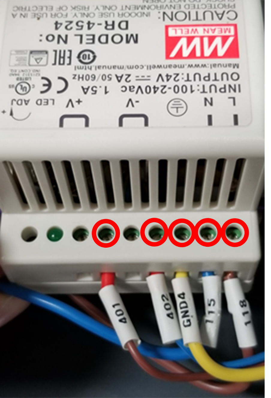
Remove the wires from the existing power supply terminals with a small, flat blade screwdriver.
-
Depending on which power supply you have, do one of the following:
-
Gray Power Supply Go to "Install the Replacement Power Supply".
-
White Power Supply Go to Step 6.
-
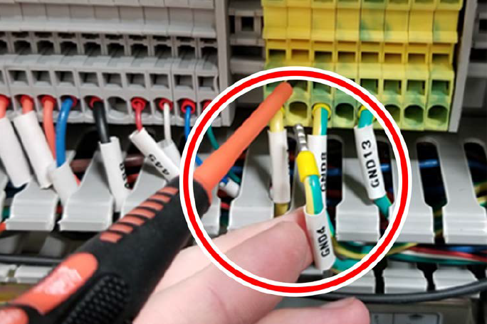
In the electrical cabinet, on the ground terminal strip, identify the GND 4 wire. Then, remove it with a small, flat-blade screwdriver. You can discard the ground wire.
Install the Replacement Power Supply
-
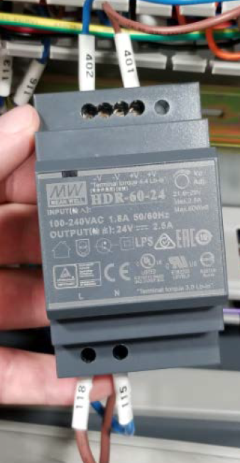
Make the wire connections on the replacement power supply:
-
Connect wire 118 (brown) to the L terminal on the new power supply.
-
Connect wire 115 (blue) to the N terminal on the new power supply.
-
Connect wire 401 (brown) to one of the V+ terminals on the new power supply.
-
Connect wire 402 (blue) to one of the V- terminals on the new power supply.
-
-
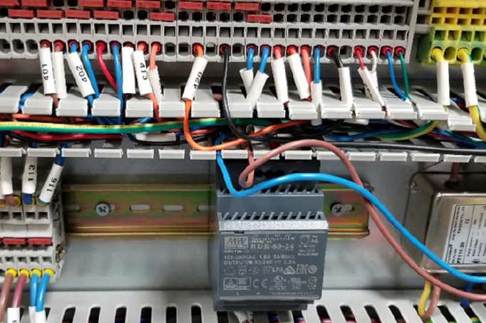
In the electrical cabinet, hold the power supply's DIN rail clip open, and mount the replacement power supply to the DIN rail.
-
Tuck the power supply's wires into the wire troughs and re-install the wire trough covers that you set aside earlier.
To view a PDF version of your manual, go to Tormach document TD10802.
If you have additional questions, we can help. Create a support ticket with Tormach Technical Support at tormach.com/how-to-submit-a-support-ticket for guidance on how to proceed.