In This Section, You'll Learn:
About the main components of the machine and how it moves.
Before operating the machine in any way, you must read and understand this section.
System Reference
To operate your machine, you must become familiar with the components of its system.
Machine Table
The machine table is 26.7" × 65" (680 mm × 1651 mm). It's a hybrid design that allows you to use:
-
Vacuum fixturing (primary)
-
Spoilboard fixturing
-
Interchangeable pallets
There are three vacuum zones, each with a pair of dowel pins (which are 6 mm in diameter), and an M8 bolt pattern. Use the dowel pins to align pallets and fixtures to the surface of the machine table; use the M8 holes to fasten pallets, fixtures, or spoilboards to the machine table.
NOTICE! Don't use the last 6 in. of phenolic table at the Y+ end of the machine as a working or load-bearing surface. If you do, it could cause damage to the phenolic table.
Spindle
The machine spindle uses an ER20 collet electrospindle.
-
Spindle Power 2 hp (1.5 kW)
-
Minimum Speed 10,000 rpm
-
Maximum Speed 24,000 rpm
About the Spindle
The machine spindle gives power to the cutting tool, which allows it to remove material from the workpiece. The spindle is driven by the spindle motor.
Operate the spindle either manually or by G-code commands (entered in the MDI Line DRO field or programmed into a G-code program).
Axes
The machine has three linear axes of motion used for machining:
-
The X-axis, which is (horizontally) along the width of the gantry.
-
The Y-axis, which is (horizontally) along the length of the machine table.
-
The Z-axis, which is (vertically) along the Z-axis linear rail plate.
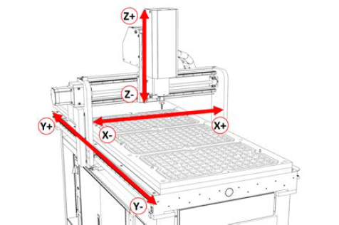
Each axis has a different limit of travel, which is the distance it moves from its reference position (G53) before reaching a soft limit:
-
X-Axis 24.75" (628 mm)
-
Y-Axis 55.75" (1416 mm)
-
Z-Axis 6.7" (170 mm)
Basic Controls Reference
To safely and effectively operate your machine, you must become familiar with how it moves. The machine has two forms of basic controls: machine controls and the PathPilot interface.
Machine Controls
The following controls energize the machine's control electronics:
-
The Main Disconnect switch, located on the left end of the electrical cabinet.
The Main Disconnect switch has two positions: OFF and ON. When it's in the OFF position, it separates the other machine control electronics from the mains electrical supply. When it's in the ON position, the other machine control electronics are able to receive power.
WARNING! Before opening the electrical cabinet for maintenance or troubleshooting, you must lockout the mains power: Turn the Main Disconnect switch to the OFF position, and secure an approved lockout device through the lockout rings at the bottom of the switch.
-
The operator box — which contains the blue Reset button and the red Emergency Stop button — located on the keyboard table (on the Controller Arm).
When pushed in, the Emergency Stop button interrupts power to the spindle and axis drives, and stops the machine’s motion. When the Emergency Stop button is twisted out, press the Reset button to enable the machine, allowing spindle and axis motion. The Reset button’s LED turns on when the machine is enabled and the spindle and axis drives receive power.
PathPilot Interface
PathPilot is the primary means by which you interact with your machine. PathPilot controls all of the automatic motion of the machine axes and spindle, as well as some accessories. The PathPilot control system consists of one of the following:
-
Controller Arm
-
Controller
-
(Optional)Jog Shuttle
-
Keyboard
-
Monitor or (Optional)Touch Screen Kit
-
Mouse
-
-
Operator Console
-
Console (with integrated touch screen)
-
(Optional) Keyboard
-
(Optional) Mouse
-
Jog pendant
-
Connectors Reference
-
A-Axis Motor Connector On the front right end of the electrical cabinet.
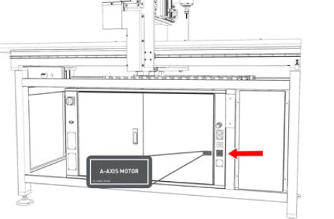
The A-axis motor connector is used to connect to a rotary 4th axis (used for indexing or continuous 4th axis machining).
-
Accessory Input (2x)
-
Accessory Input 1 On the operator side of the rear Z-axis cover.
-
Accessory Input 2 Below the Main Disconnect switch on the electrical cabinet.
-
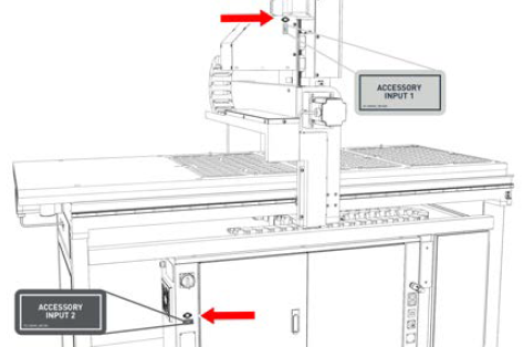
The two accessory inputs are used to connect accessories (like probes, tool setters, and tool touch plates) to the machine.
-
Accessory Power Port (2x) On the front right end of the electrical cabinet.
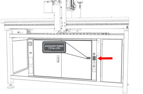
The two IEC-320 accessory power ports are used to supply power to peripheral accessories (like the PathPilot controller and monitor). These outlets output 115 Vac ±10%.
-
Chiller Alarm Input On the side of the left end of the electrical cabinet.
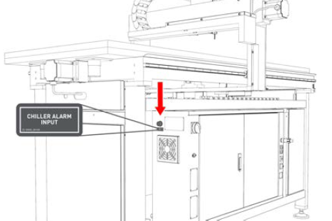
The chiller alarm input connects the alarm status feedback from the spindle chiller to the machine control system. This feedback allows the machine control system to stop the spindle from running while the chiller isn't working.
-
Compressed Air Line At the back end of the machine underneath the phenolic table.
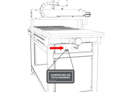
The compressed air line is used to supply accessories and components with compressed air.
-
Controller Communications Port On the front right end of the electrical cabinet.
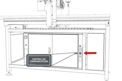
The controller communications port is used to connect the PathPilot controller to the machine. The controller communications port (and the cable that connects to it) sends all communication between the PathPilot interface and the machine.
-
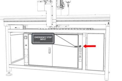
Emergency Stop Input On the front right end of the electrical cabinet.
Looking for more information?
This is a section of the 24R operator's manual. To view the whole manual, go to Tormach document UM10564.
If you have additional questions, we can help. Create a support ticket with Tormach Technical Support at tormach.com/how-to-submit-a-support-ticket for guidance on how to proceed.