Background
The spindle is the rotating assembly that holds the tool/tool holder. It’s powered by a motor that can either be integral or - like most of our machines - external, relying on a belt and pullies to transmit the power.
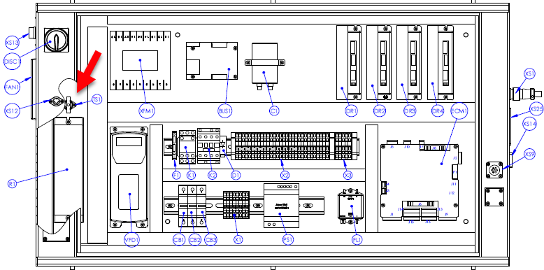
The VFD that controls the motor doesn't power on with the machine. Instead, it turns on after you command the spindle to start.
Tools
-
Multimeter
-
Adjustable wrench
-
Screwdriver set
Verify speed was commanded properly
Reason: Commanded speed did not execute.
To command a specific RPM in PathPilot, you enter your desired speed, and then you MUST press enter for the machine to accept the commanded speed. Then proceed to hit FWD or REV.
The Variable Frequency Drive (VFD) isn’t getting power
Reset the brake resistor’s thermal switch
Reason: The thermal switch tripped and needs to be reset.
-
Reset the thermal switch (TS1) as follows:
-
Power off the machine.
-
Allow the brake resistor to cool.
-
Press the reset button (between the thermal switch’s two terminals) to reset the thermal switch.
-
Verify that the spindle run/start is working
Reason: The spindle start signal from the control board isn’t working.
-
Examine wires 420 and 422 for 24 Vdc on wires J10.1 and J10.3, respectively.
-
Start the spindle and listen for a soft, audible click on the control board. If you hear this click (from a relay contact on the board), the machine control board is functioning properly. If you don't hear the click:
-
Verify that there's 24 Vdc measured from wire 421 to wire 422. Make a jumper wire and, carefully,
momentarily jumper wires 422 and 420.-
If contactor K2 pulls in (you will hear an audible clunk) while you have the jumper on but drops out as soon as you remove the jumper, review the previous solutions to inspect why the K2 isn’t holding.
-
If K2 stays powered on, the control board is not passing the run signal to the circuit. The control board passes 24 Vdc from wire 422 to 420 via a relay to create the start pulse. Measure wire 422 for 24 Vdc power. If present, the control board or wire 420 connected to J10.3 is defective. Power off the machine, and jumper J10.1 to J10.3 Power on the machine and check the VFD for a display. If the VFD reads rdy, the control board is defective. If not, wire 420 may be broken. Lift the connections of wire 420 at the control board and K2 and measure continuity.
-
-
Verify that the VFD is getting power
Reason: The VFD is defective.
-
Using a multimeter, confirm you have power getting to the VFD between L1 and L3.
-
If there is power but nothing on the display, contact Tormach Technical Support.
-
If there is no power, review the previous solutions to try and re-establish power.
-
-
If there is a trip or error code that does not clear after power cycling the machine, contact Tormach Technical Support.
Measure the motor resistance (Ω)
Reason: The motor has an internal short and is malfunctioning.
-
Power off the machine.
-
Wait 30 seconds, and then remove the U, V, and W wires from the VFD terminals.
-
Measure the resistance between the following wires to see if it is approximately 2-4 Ω:
-
Wires U and V
-
Wires U and W
-
Wires V and W
-
-
Measure the resistance between the following wires to verify that it is >1M Ω or OL, indicating that there is no short:
-
Wire U and Ground (bare exposed metal or a green and yellow wire with a PE label)
-
Wire V and Ground (bare exposed metal or a green and yellow wire with a PE label)
-
Wire W and Ground (bare exposed metal or a green and yellow wire with a PE label)
-
-
Numbers outside of the specified range indicate that the motor or its wiring is bad and needs to be replaced. Perform the same test on the motor cable connector, if applicable.
Identify the VFD code and solution
Reason: The VFD is tripped and showing an error.
|
Trip Code |
Condition |
Likely Cause |
|---|---|---|
|
boot |
Boot from SD card. |
Displayed for first 5-6 seconds after power up when booting from SD card. (M200/C200 only) |
|
UU |
DC-BUS under-voltage. |
This happens when the VFD is powered down or loses power. |
|
OU |
DC-BUS over-voltage. |
Braking resistor failed open or wiring connection open between the VFD and the resistor. Resistance to measure 70 ohms. |
|
OI.ac |
VFD output instantaneous over current. |
Phase-to-phase or phase-to-ground short on output of VFD to motor. This trip code cannot be reset until 10 seconds after the trip was initiated. |
|
OI.br |
Braking resistor instantaneous over current. |
Braking resistor shorted or partially shorted out or short in wiring between the VFD and the resistor. Resistance to measure 70 ohms. Check brake resistor wiring. |
|
It.br |
I2t (power) on braking resistor. |
Excessive braking resistor energy caused by too frequent and too severe deceleration cycles or AC supply voltage too high. |
|
IT.ac
|
I2t (power) on VFD output current (used to
|
Spindle motor is working too hard. Ensure that the spindle is not jammed or sticking. Consider running the spindle motor at half speed for 10 minutes with no load to cool the motor down. |
|
Oht.C |
VFD is working too hard and stops to cool power electronics down to prevent failure. |
Spindle motor is working too hard. Stop running the spindle but leave the VFD power on and let the power electronics cool down. |
|
Oht.I
|
Heat sink temperature is too high because the VFD is working too hard and stops to cool power electronics down to prevent failure. Cabinet may also be too hot. |
Spindle motor is working too hard or it is too hot in work location. Stop running the spindle but leave the VFD power on and let the power electronics cool
|
|
HF01 through HF23 |
Hardware fault. |
Failed drive. |
Inspect the VFD program
Reason: The wrong program has been loaded or is running on the VFD.
-
Identify your specific VFD in the table below, and follow the instructions to identify what program it is running.
-
If the program does not match your machine and machine configuration, contact Tormach Technical Support.
|
VFD Model |
How to inspect the VFD program |
|---|---|
|
M200 and C200 |
|