Unpack the Machine Crate
Tools and Items Required
-
Pallet jack
-
Safety eyewear that meets ANSI 787+
-
Snips
-
Socket wrench and 8 mm (5/16 in.) socket
-
Work gloves
CAUTION! Sharp Objects Hazard: Before opening the shipping crate, you must put on work gloves and safety eyewear that meets ANSI Z87+. If you don't, the shipping crate and steel straps could cut you, causing serious injury.
-
Put on work gloves and eye protection.
-
Cut and remove the steel straps on the shipping crate with snips.
-
Remove the screws from the shipping crate with a socket wrench and an 8 mm (5/16 in.) socket. Start with removing the screws securing the top, followed by the four sides.
NOTE: To access the screws on the top of the shipping crate, you may need a ladder.
-
Remove and discard the plastic wrap from the machine.
-
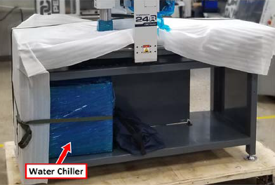
Cut and remove the shipping straps securing the water chiller and the stand end panel to the machine stand, and set both aside for later installation.
-
Remove the tool bag from the machine stand, and set it aside for later use.
The Tormach tool bag contains the following tools and items:
-
6 mm Vacuum Gasket (PN 50362), 6 m
-
18 mm - 21 mm Wrench (PN 50358)
-
30 mm - 27 mm Wrench (PN 50357)
-
Adjustable Wrench (PN 50359)
-
Dust Shoe Assembly (PN 50625)
-
ER20 Collet Nut
-
Grease Gun (PN 50360)
-
Metric Hex Wrench Set (PN 50361)
-
Operator box
-
Remove and discard all protective shipping materials from the machine, and cut and remove any remaining shipping straps.
-
Remove the desiccant packet from the Z-axis. If it's not on the Z-axis, it may have fallen onto the machine table during shipping.
-
Inspect the item(s):
-
Photograph any damage that may have occurred during shipping.
-
Verify the received goods against the packing list.
If there is any damage or shortages, you must contact Tormach within 30 days of receipt. Create a support ticket with Tormach Technical Support at tormach.com/how-to-submit-a-support-ticket for guidance on how to proceed.
Lift and Move the Machine
Tools and Items Required
-
2 in. × 6 in. × 8 in. board (block), 40
-
4 in. × 4 in. × 6 ft board (support), 2
-
8 mm wrench
-
Adjustable wrench (or, if desired, a 22 mm wrench)
-
Pallet jack
The easiest way to lift and move the machine off of the pallet is to use a forklift. If you don't have a forklift available, we recommend lifting the machine with 4 in. × 4 in. × 6 ft boards (supports) and 2 in. × 6 in. × 8 in. boards (blocks).
To lift and move the machine:
-
Move the machine's pallet as close as possible to the desired location with a pallet jack.
-
The machine is secured to the pallet with two screws in the base of each foot. Remove the screws from the pallet with an 8 mm wrench.
NOTE: If you have a forklift, use it to lift and move the machine off of the pallet now. When finished, go to "Level the Machine".
-
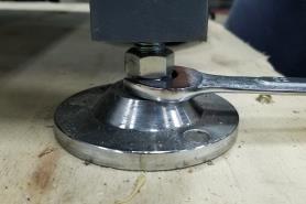
Verify that the top nut on each machine foot is loose.
NOTE: The top nut is used to lock the height of the machine in place (which you'll do after you're done leveling the machine). The bottom nut raises or lowers the machine.
-
Raise the machine up about 1 in. by turning the lower nut on each machine foot with an adjustable wrench (provided in the tool bag).
This raises the machine up to make room for the supports.
Tip! You can also use a 22 mm wrench, if you have it available.
-
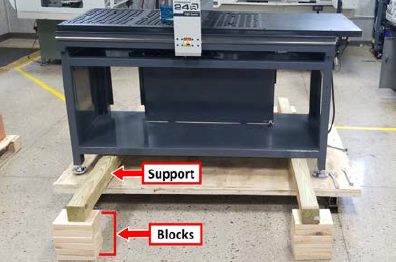
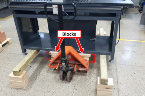
Put two supports on the pallet so that they're approximately 6 in. from each end of the machine stand. Verify that there's enough room between the supports for the pallet jack.
-
Stack blocks under each end of the supports as shown in the following image.
WARNING! Transportation and Lift Hazard: Before moving the machine, you must confirm that all persons are clear of the area below the machine. Qualified professionals must transport, lift, and move the machine. Moving parts can entangle, pinch, or cut you, causing death or serious injury.
-
Lower the machine with an adjustable wrench until the weight of the machine is completely held by the supports. Verify that the feet aren't touching the pallet.
-
Slowly remove the pallet from under the machine.
-
Lift the machine off of the supports with a pallet jack. If your pallet jack doesn't lift high enough to move the machine, stack blocks on it. You must verify that the additional blocks are placed evenly on the pallet jack, and that they're beneath all four lifting points on the machine before attempting to raise the pallet jack.
-
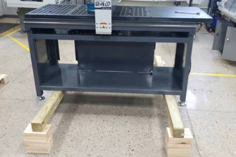
Once the weight of the machine is fully supported by the pallet jack, begin lowering the machine onto the floor:
-
Remove two of the blocks from each end of the supports.
-
Slowly lower the pallet jack until the weight of the machine is fully supported by the supports.
-
Remove two of the blocks from the pallet jack.
-
Lift the machine off of the supports with the pallet jack.
-
-
Repeat Step 10 until the weight of the machine is entirely on the floor.
Level the Machine
Tools and Items Required
-
24 mm wrench
-
Adjustable wrench
-
Carpenter's level
-
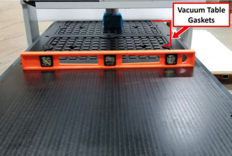
Put a carpenter's level on the machine table. Verify that the level is flat on the table, and isn't on the vacuum table gaskets.
-
Raise or lower each foot by turning the lower nut with an adjustable wrench to level the machine in the X and Y directions.
-
Examine all four feet and verify that each foot touches the floor.
-
Tighten the top nut (the jam nut) on each foot with a 24 mm wrench.
Looking for more information?
This is a section of the 24R operator's manual. To view the whole manual, go to Tormach document UM10564.
If you have additional questions, we can help. Create a support ticket with Tormach Technical Support at tormach.com/how-to-submit-a-support-ticket for guidance on how to proceed.