Purpose
This document gives instructions on installing the 24R Z-Axis Brake Retrofit Kit on machines RA10001 through RA10096, which do not include a Z-axis brake.
IMPORTANT! This kit is required to use an automatic tool changer (ATC) on machines RA10001 through RA10096. You must install this kit before you begin to install the ATC.
Product Information
Product: 24R Z-Axis Brake Retrofit Kit (PN 51136)
|
Quantity |
Description |
|
1 |
24R Z-Axis Brake Cable Assembly (PN 51138) |
|
1 |
Z-Axis Motor with Z Brake (PN 51133) |
NOTE: If any items are missing, we can help. Create a support ticket with Tormach Technical Support at tormach.com/how-to-submit-a-support-ticket for guidance on how to proceed.
Required Tools
This procedure requires the following tools. Collect them before you begin.
-
3 mm hex wrench
-
4 mm hex wrench
-
6 mm hex wrench
-
An assistant to help you
-
Flat-blade screwdriver, small
-
Wood blocks
Before You Begin
Update PathPilot
If you haven't yet done so, you must update your controller to the latest version of PathPilot.
-
From the PathPilot interface, on the Status tab, select Update.
Installation Procedure
If your 24R router serial number is between RA10001 and RA10096, you must install the Z-axis brake. Some machines within that serial number range require an additional installation of a Z-axis brake cable.
-
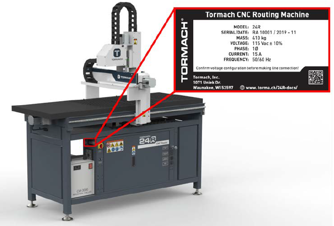
Find your machine's serial number plate on the side of the electrical cabinet.
-
Use the following table to determine which procedure to start with, depending on your specific machine.
|
Serial Number |
Go to... |
|
RA10001 through RA10084 |
|
|
RA10085 through RA10096 |
|
|
RA10097 or higher |
The Z-axis brake is pre-installed at the factory, and you don't need to follow any procedures in this document. |
Installation
Update Wire 487 From the Machine Control Board
-
Power on the machine and the PathPilot controller.
-
Turn the Main Disconnect switch to ON on the side of the electrical cabinet.
-
Twist out the machine's red Emergency Stop button, which enables movement to the machine axes and the spindle.
-
Press the Reset button.
-
Bring the machine out of reset and reference it.
-
-
Jog the X-axis to about the middle point of travel (12 in.).
-
Jog the Y-axis about 24 in. in the positive direction.
-
Jog the Z-axis down to the end of travel.
-
Remove any cutting tools from the spindle.
WARNING! Electrical Shock Hazard: You must power off the machine before making any electrical connections. If you don't, there's a risk of electrocution or shock.
-
Power off the machine and the PathPilot controller.
-
Push in the machine's red Emergency Stop button, which removes power to motion control.
-
From the PathPilot interface, select Exit.
-
Turn the Main Disconnect switch to OFF on the side of the electrical cabinet.
-
Remove the power plug(s) from the wall outlet. If your system is hardwired, isolate the machine by opening its circuit breaker(s).
-
Follow correct lockout/tagout procedures.
-
-
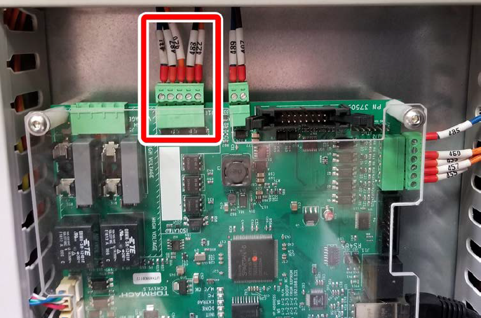
In the electrical cabinet, on the top of the machine control board, identify the J10 connector.
-
Unplug the connector from the board. Remove wire 487 and wire 488 from the connector with a small, flat-blade screwdriver.
-
Remove the necessary wire trough covers and trace wire 487 and wire 488 back to the terminal block strip.
-
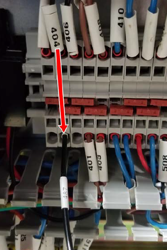
Disconnect wire 488 from the terminal block with a small, flat-blade screwdriver. Discard the wire.
-
Connect the loose end of wire 487 to the +24 Vdc by inserting it into the open port of the terminal block connected to wire 404.
Install the Z-Axis Brake Cable
IMPORTANT! If your machine's serial number is between RA10085 and RA10096, your machine already has a Z-axis brake cable installed. Skip this section and go to "Remove the Existing Z-Axis Motor".
In this section, you'll remove the vacuum table off of the casting to route the Z-axis cable to the electrical cabinet. To simplify this procedure, we recommend:
-
Asking an assistant to help you.
-
Setting up a table or a set of saw horses to temporarily hold the vacuum table while you work on the Z-axis brake cable routing.
Route the Z-Axis Brake Cable to the Electrical Cabinet
-
Remove the M8 screws securing the vacuum table to the machine with a 6 mm hex wrench. Set the screws aside.
-
From the end of the machine, slide the vacuum table off of the casting.
-
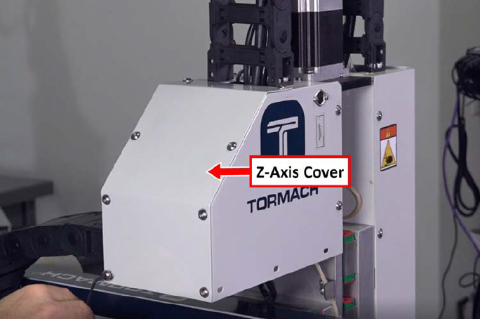
From the back of the gantry, remove the screws securing the lid to the rear of the Z-axis cover with a 3 mm hex wrench. Set the cover and screws aside.
-
Remove the five M5 screws on the cable tray cover on the back of the gantry and the five M5 screws from the cable tray cover on the side of the gantry with a 3 mm hex wrench. Set the screws and covers aside.
-
Find the 24R Z-Axis Brake Cable Assembly (PN 51138) provided in this kit.
-
Wrap the ends of the cable together with electrical tape.
-
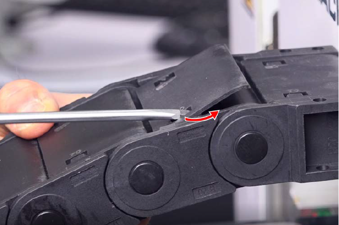
To route the cable through the X-axis energy chain, you must remove every other energy chain cover. Put small, flat-blade screwdriver into the left rectangle opening and pry up. Then, pry up on the right rectangle opening. Lift the cover and set it aside.
-
Repeat Step 7 for every other energy chain cover. The top and bottom energy chain covers are different sizes, so keep them separate for re-installation.
-
Begin routing the brake cable through the X-axis energy chain and then down the side of the gantry.
-
Replace the energy chain covers that you set side earlier by sliding them back into place and snapping both the top and the bottom to secure them.
-
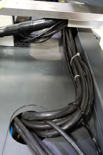
Route the cable down the side of the gantry, through the cable tray on the bottom of the gantry, and then into the Y-axis energy chain closest to the electrical cabinet.
-
Remove any necessary energy chain covers on the Y-axis energy chain with a short, small, flat-blade screwdriver. Set aside the covers.
-
Route the cable through the Y-axis energy chain and then toward the hole on the top of the electrical cabinet.
-
Replace any energy chain covers that you set aside earlier.
-
Route the cable through the hole in the top left of the electrical cabinet and then through the wire troughs.
Make Electrical Connections
-
Route wire 509 and wire 510 to the machine control board, and then unwrap the electrical tape.
-
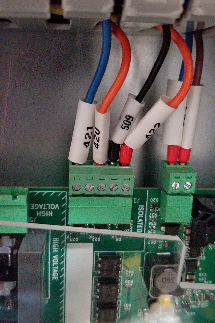
Connect wire 509 to pin 2 on the J10 connector with a small, flat-blade screwdriver.
-
Route wire 510 toward the top of the 24 Vdc power supply.
-
Find the security pin on the bottom of the power supply, and release it with a small, flat-blade screwdriver. You can tsen lift the power supply off of the DIN rail to make the wire connections.
-
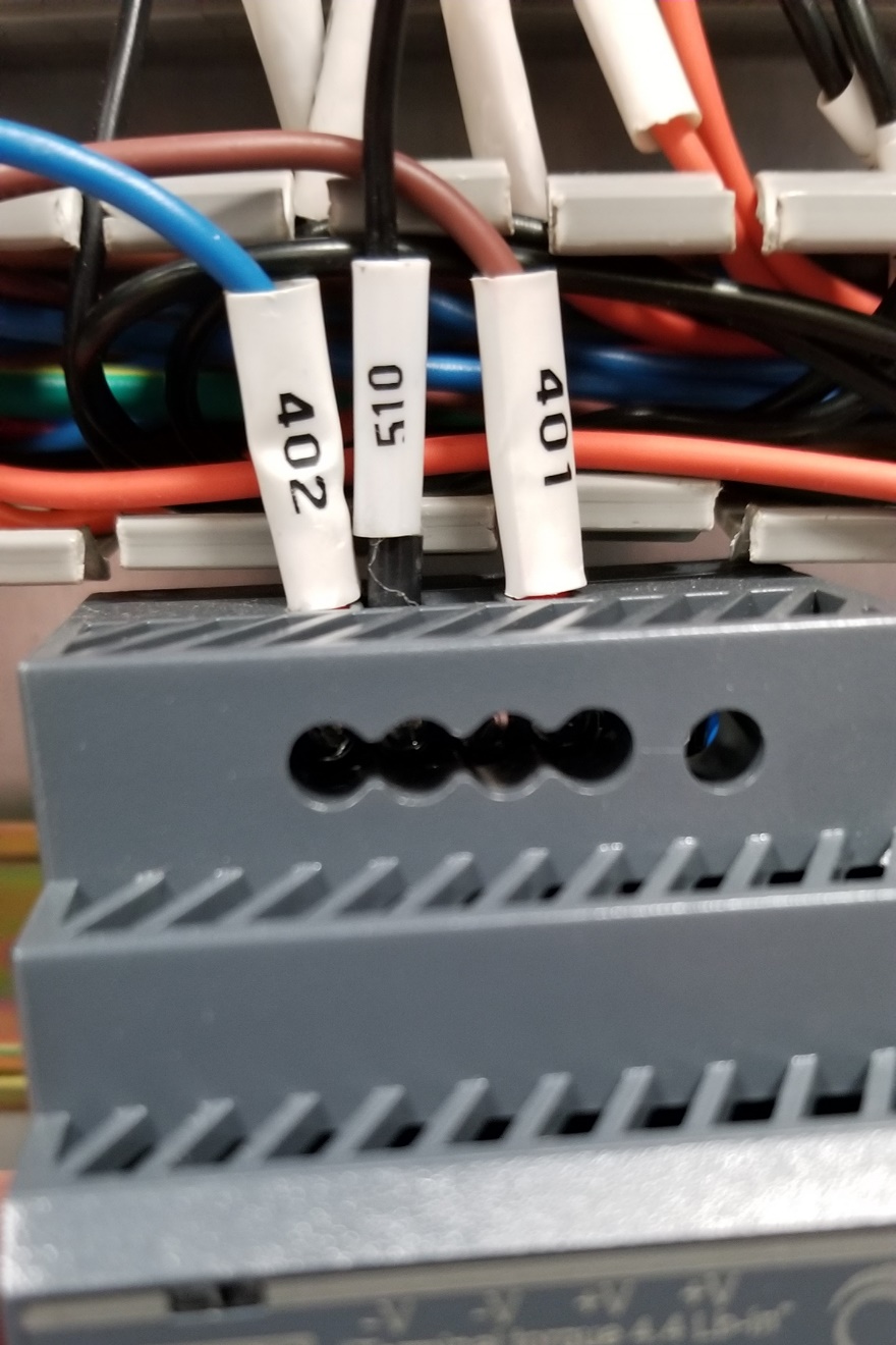
Connect wire 510 to the empty V- terminal on the power supply with a small, flat-blade screwdriver.
-
Re-seat the power supply onto the DIN rail, and then re-seat the security pin with a small, flat-blade screwdriver.
-
Re-install wire troughs into the electrical cabinet.
Remove the Existing Z-Axis Motor
-
If you haven't yet done so, you must first power off the machine and the PathPilot controller.
WARNING! Electrical Shock Hazard: You must power off the machine before making any electrical connections. If you don't, there's a risk of electrocution or shock.
-
Power off the machine and the PathPilot controller.
-
Push in the machine's red Emergency Stop button, which removes power to motion control.
-
From the PathPilot interface, select Exit.
-
Turn the Main Disconnect switch to OFF on the side of the electrical cabinet.
-
Remove the power plug(s) from the wall outlet. If your system is hardwired, isolate the machine by opening its circuit breaker(s).
-
Follow correct lockout/tagout procedures.
-
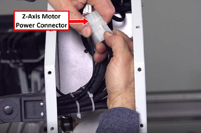
-
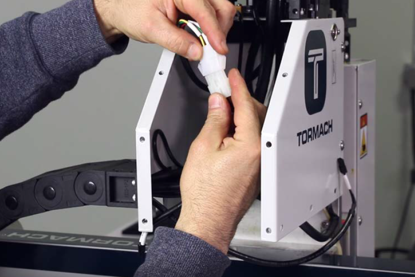
Locate the Z-axis motor power connector in the rear of the Z-axis cover and disconnect it.
-
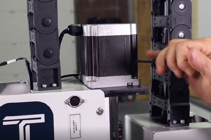
From the Z-axis motor, remove the four M6 screws securing it in place with a 4 mm hex wrench. Set the screws aside.
-
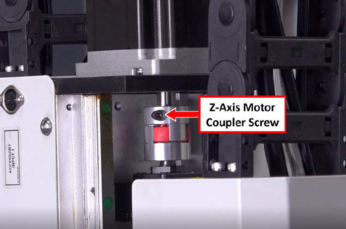
Locate the Z-axis motor coupler. If you can access the screw securing the coupler to the Z-axis motor shaft, loosen it with a 4 mm hex wrench. If you can't access the screw, go to Step 6.
-
Put a 4 ft wood board under the spindle head. Slowly lift the board up to move the spindle head up and rotate the coupler. Put a shim under the board to keep it in place while you loosen the screw securing the coupler to the Z-axis motor shaft with a 4 mm hex wrench.
-
Lift and remove the Z-axis motor and discard it.
Install the Replacement Z-Axis Motor with Brake
-
Find the Z-axis motor with Z brake provided in the kit.
-
With the motor's wires facing the back of the machine, slip the motors shaft into the coupler on the ball screw and set the motor on top of the Z-axis motor mount.
-
Tighten the coupler onto the shaft of the motor with a 4 mm hex wrench.
-
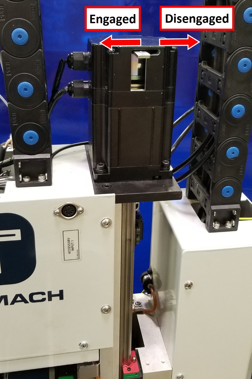
Verify that the Z-axis brake's manual override lever is slid to the left (in the engaged position). If it's not, slide the lever to engage the brake.
-
Secure the Z-axis motor to the motor mount with the four M6 screws from the previous step.
-
Identify the Z-axis motor power connector in the rear Z-axis cover and connect it to the motor.
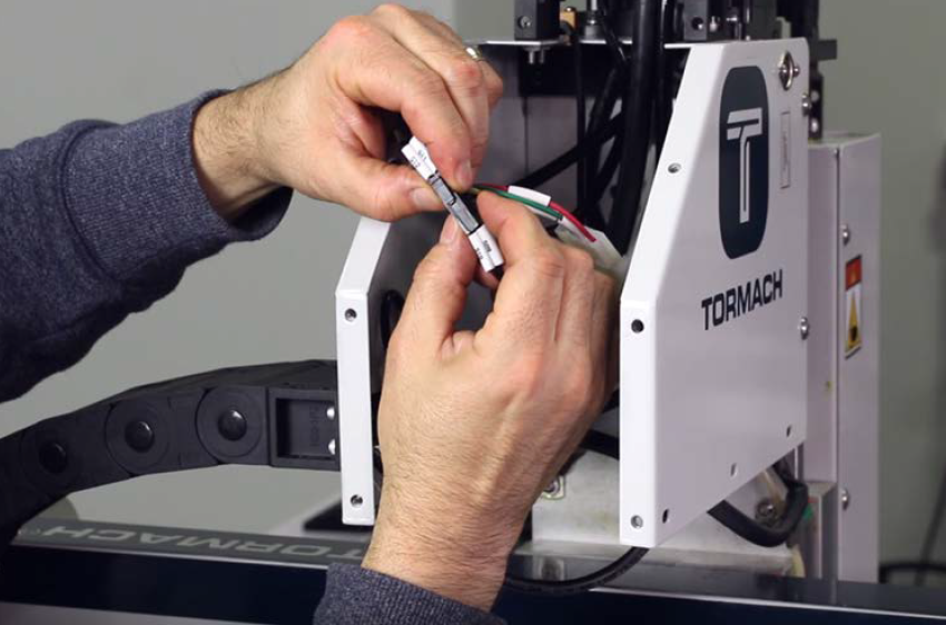
-
Connect the Z-axis brake cable to the Z-axis motor’s brake connector in the rear Z-axis cover.
-
Re-install the following items with the parts that you set aside earlier:
-
Vacuum table
-
Rear Z-axis cover
Verify the Installation
-
Turn the Main Disconnect switch to ON on the side of the electrical cabinet.
In the electrical cabinet, examine the axis motor drives to determine if the green LEDs are illuminated.
-
If the green LEDs are OFF, continue to the next step.
-
If the green LEDs are ON, power off the machine and go to "Troubleshooting" > Problem: The Emergency Stop button doesn't work.
-
Twist out the machine's red Emergency Stop button, which enables movement to the machine axes and the spindle.
Examine the Reset button to determine if the blue LED is already illuminated.
-
If the blue LED is OFF, continue to the next step.
-
If the blue LED is ON, power off the machine and go to "Troubleshooting" > Problem: The Emergency Stop button doesn't work.
-
Press the Reset button.
-
From the PathPilot interface, bring the machine out of reset.
-
On the keyboard, press the Page Up key to raise the spindle head off of the wooden block.
-
From the PathPilot interface, reference the Z-, X-, and Y-axis.
The Z-axis motor should operate smoothly and sound like the other two axis motors. If the Z-axis motor sounds different, go to "Troubleshooting".
Troubleshooting
|
Problem: Spindle head falls after installing the new motor with brake when the machine is powered off. |
|
|
Probability |
How-To Steps |
|
High |
Power off the machine. On the top of the Z-axis motor, push the manual break override lever to the left. The brake switches into automatic mode, and engages the brake when the machine is powered off. |
|
Problem: The Z-axis motor makes grinding noises during operation. |
|
|
Probability |
How-To Steps |
|
High |
Verify that the latest version of PathPilot is installed on your controller. In the rear Z-axis cover, check the Z-axis motor connector to verify that it's properly connected and all wires are seated into the connector. In the electrical cabinet, inspect wires 509 and 510 to verify that they are properly connected. For information, see "Electrical Schematics". |
|
Problem: The Emergency Stop button doesn't work. |
|
|
Probability |
How-To Steps |
|
High |
Verify that any of the following symptoms occur: The blue Reset LED is always on, even when the Emergency Stop button is pressed in. The green LEDs on the axis drives are always on, even when the Emergency Stop button is pressed in. The green LED on the K1 relay is always on, even when the Emergency Stop button is pressed in. In the electrical cabinet, inspect wires 509 and 510. Verify that they are connected to the correct location inside the electrical cabinet: Wire 509 connects to Pin 2 on the J10 connector of the ECM1 machine control board. Wire 510 connects to -V on the 24 Vdc power supply. If wires 509 and 510 are connected to the correct locations in the electrical cabinet, refer to the troubleshooting section of the 24R operator’s manual. |
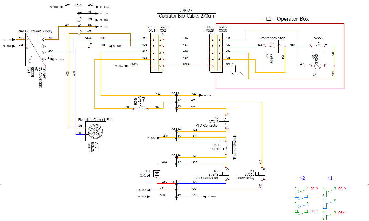
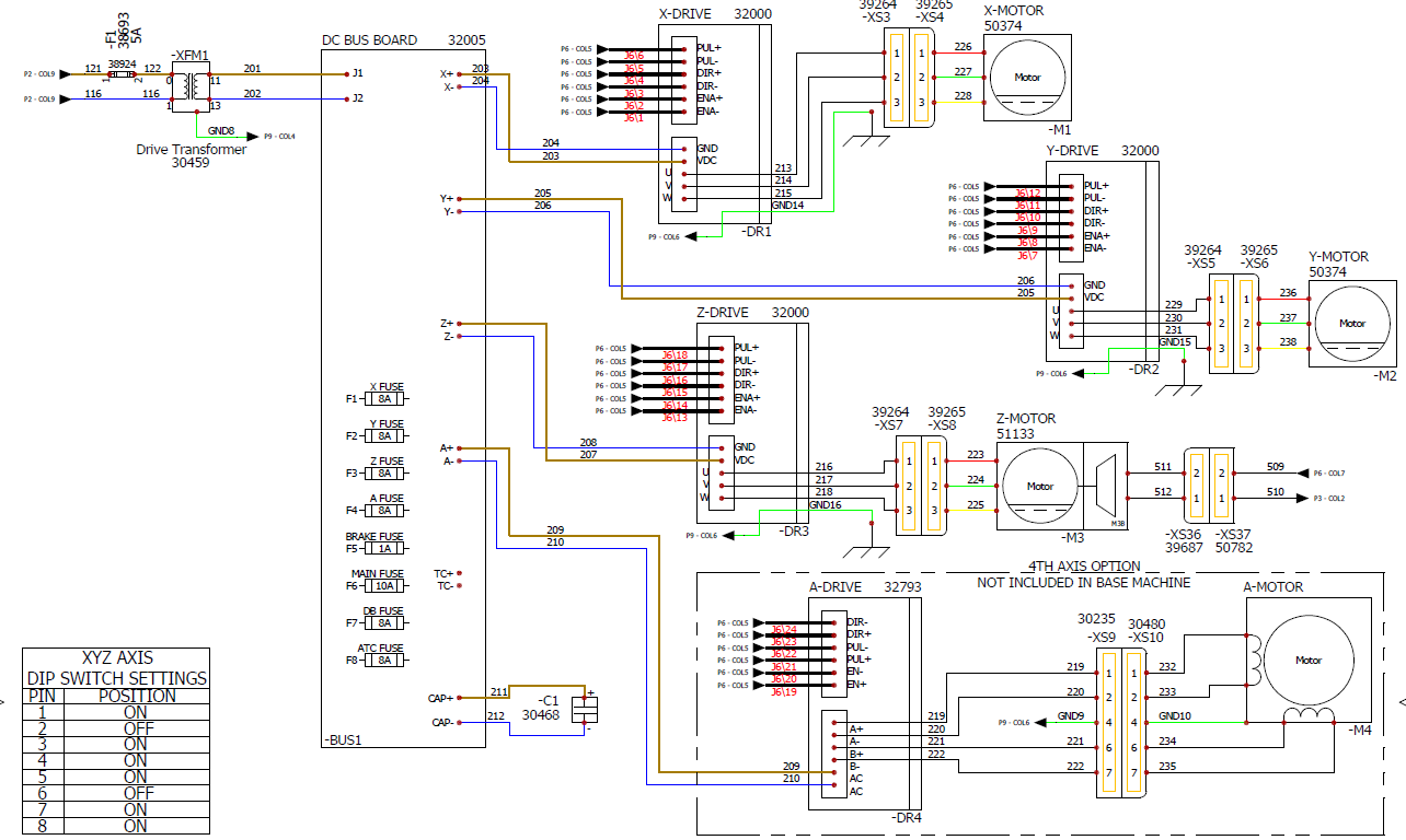
Electrical Schematics
24 Vdc Controls (Sheet 3)
Axis Drive Bus (Sheet 4)
To view a PDF version of your manual, go to Tormach document TD10801.
If you have additional questions, we can help. Create a support ticket with Tormach Technical Support at tormach.com/how-to-submit-a-support-ticket for guidance on how to proceed.