Install the Controller Arm
Tools and Items Required
-
#5 drill bit
-
4 mm hex wrench
-
6 mm hex wrench
-
8 mm hex wrench
-
17 mm hex wrench
-
17 mm socket wrench
-
21 mm wrench
-
Dead-blow hammer (or similar)
-
Drill
-
Phillips screwdriver
-
Pry bar
-
Tape
CAUTION! Sharp Objects Hazard: Before opening the shipping crate, you must put on work gloves and safety eyewear that meets ANSI Z87+. If you don't, the shipping crate and steel straps could cut you, causing serious injury.
-
Put on work gloves and eye protection.
-
Open the Controller Arm crate with a pry bar.
-
Find the mounting pad on the machine stand.
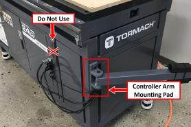
WARNING! Crush Hazard: Only install the Controller Arm on the mounting pad at the front end of the machine. If there's a mounting pad next to the electrical cabinet on the machine stand, don't use it. If you do, there's a risk of entrapment between the Controller Arm and the machine's moving parts.
-
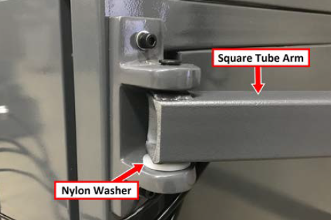
Secure the square tube arm to the machine stand with two M8 socket head cap screws, two M8 flat washers, two M8 lock washers, and a 6 mm hex wrench. Verify that the white nylon washer is located toward the bottom of the mounting pad.
-
Put the monitor post into the square tube arm. Verify that the monitor bracket is toward the top, and that the threaded holes face the holes in the square tube arm.
-
Tighten the cross bolt on the square tube arm with a 17 mm socket wrench and a 17 mm hex wrench.
-
With a 21 mm wrench, remove the monitor bracket from the Controller Arm, and rotate it so that the largest mounting plate is facing up.
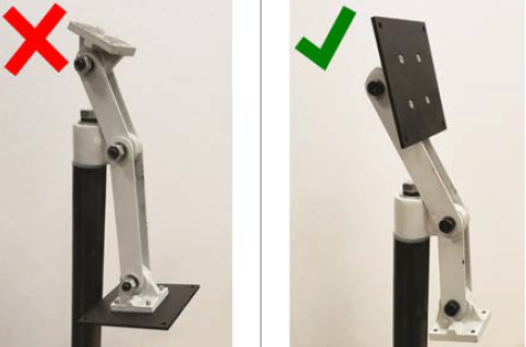
NOTE: The largest mounting plate is for the monitor, and the smallest mounting plate is for the keyboard tray.
-
Tighten the three pivot bolts on the monitor bracket with an 8 mm hex wrench and a 16 mm wrench.
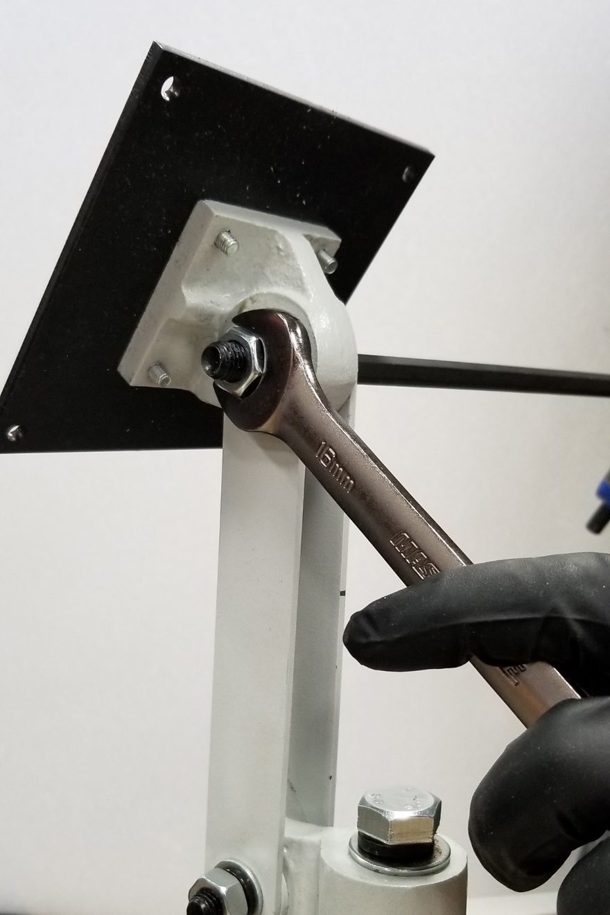
Tip! This makes it easier to install the monitor, which you'll do later in this installation procedure.
-
Tap the end plug into the square tube arm with a dead-blow hammer (or similar).
-
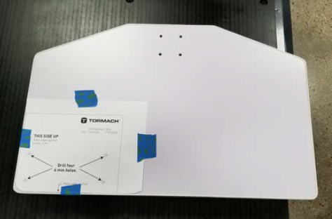
Find the operator box drill template (provided in the machine owner's kit). Put the template on the operator box, and verify that the holes on the operator box align with the holes on the template. If they don't, trace the correct hole pattern on the template.
-
Tape the template to the keyboard tray as shown in the following image. This indicates the location to mount the operator box, which you'll do later in this procedure.
-
Drill the four holes through the template and into the keyboard tray with a drill and a #5 drill bit.
-
Remove the template from the keyboard tray, and then discard it.
-
Secure the keyboard table to the monitor bracket with four M5 socket head cap screws, four M5 flat washers, four M5 split lock washers, and a 4 mm hex wrench.
-
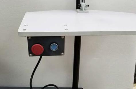
Find the operator box (in the tool bag), and mount it to the bottom of the keyboard table with four M5 × 25 mm screws and four M5 nuts (provided in the machine owner's kit).
-
Route the loose end of the cable from the operator box down the monitor post, through the openings in the square tube arm, and toward the electrical cabinet.
-
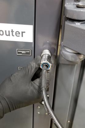
Connect the cable from the operator box to the Emergency Stop Input port on the front right end of the electrical cabinet. Tighten the locking collar to secure the cable.

-
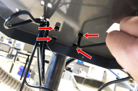
Attach four wire tie mounts to the monitor post with four 4 mm flat head machine screws and a Phillips screwdriver.
Install the Controller
Depending on your machine configuration, do one of the following:
-
If You Have a PathPilot Controller Go to "Install the Monitor".
-
If you have a PathPilot Operator Console Go to "Install the PathPilot Operator Console".
Install the PathPilot Operator Console
Tools and Items Required
-
16 mm wrench
-
Metric hex wrench set
-
Phillips screwdriver
-
Put the operator console against the monitor mounting plate and align the holes. Attach the operator console and monitor mounting plate together with four M4 × 12 mm socket head cap screws (provided with the operator console).
-
Attach the keyboard tray to the lower controller arm mount with an 8 mm hex wrench.
-
Adjust the operator console and the keyboard tray so that the two holes on the underside of the operator console line up with the holes on the keyboard tray.
-
Attach the keyboard tray to the operator console with two M3 Phillips screws (provided in the controller box) and a Phillips screwdriver.
-
Put the operator console's power supply into the power supply bracket (provided in the operator console box), and attach the assembly to the underside of the keyboard tray with M3 Phillips screws and a Phillips screwdriver.
-
Connect the 12 ft power cable to the power supply.
-
Use the three pivot bolts on the controller arm monitor bracket to adjust the position of the operator console and the keyboard tray to your desired angle with a 3 mm hex wrench and 16 mm hex wrench.
-
If you have any of the following optional USB accessories, connect them to any USB port on the operator console:
-
Keyboard
-
Mouse
-
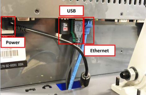
Connect the WiFi dongle to any USB port on the operator console.
-
Connect the Ethernet cable to the Ethernet port on the operator console.
-
Connect the barrel end of the power supply cable to the Power Supply port on the operator console.
-
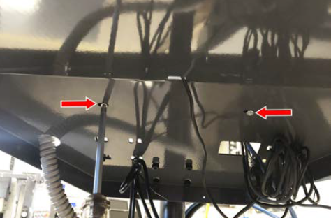
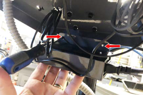
Route the loose ends of the USB, Ethernet, and power supply cables through the square hole in the keyboard tray. Then, use the cable tie holes to secure the loose power supply and USB cables.
Tip! If you're using a mouse, we recommend leaving some slack for it to move freely.
-
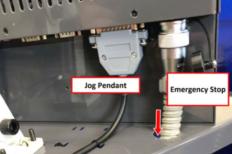
Connect the jog pendant cable and the Emergency Stop cable to the operator console.
-
Connect the cable from the operator box to the Emergency Stop Input port on the front right end of the electrical cabinet. Tighten the locking collar to secure the cable.
-
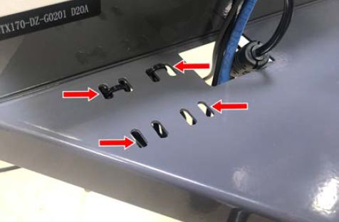
Route the loose end of the operator console's 12 ft power cable, and the Ethernet cable down the controller arm. Then, route the cables through the slots in the square tube arm that's connected to the machine stand.
-
On the right side of the machine, connect the loose ends of the cables as follows:
-
Connect the operator console's power cable to any of the Accessory power outlets.
-
Connect the Ethernet cable to the Controller Communications port.
-
-
Secure the cables to the wire tie mounts that you installed on the round monitor post with four 4 in. cable ties.
Install the Monitor
Tools and Items Required
-
3 mm hex wrench
-
8 mm hex wrench
-
16 mm wrench
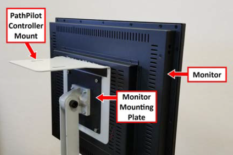
The PathPilot controller mount allows you to install the PathPilot controller behind the monitor (which is attached to the Controller Arm).
NOTE: If you're using a Touch Screen Kit (PN 35575), you must first remove the stock mounting bracket from the back of the monitor.
-
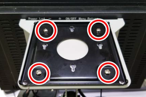
Put the PathPilot Controller VESA Mount (PN 50382) against the monitor mounting plate. Then, put the monitor on the other side of the PathPilot controller mount, and align the holes on the three components.
-
Attach the monitor, PathPilot Controller VESA Mount, and monitor mounting plate together with four M4 × 12 mm socket head cap screws (provided with the PathPilot Controller VESA Mount).
-
Adjust the position of the monitor and the keyboard tray with an 8 mm hex wrench and a 16 mm wrench. Once complete, securely tighten the pivot screws.
Install the PathPilot Controller
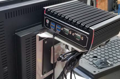
The PathPilot controller attaches to the top of the PathPilot Controller VESA Mount and behind the monitor.
-
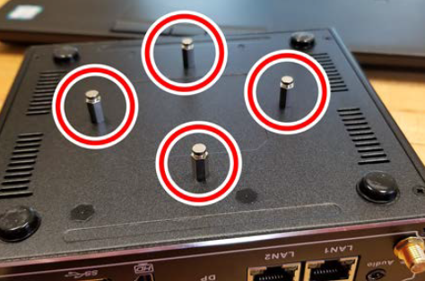
Put four standoffs into the controller and tighten them by hand.
-
Find the four M4 screws and the VESA plate included with the controller. Then, mount the VESA plate to the PathPilot Controller VESA Mount (PN 50382). Make sure to put it flat side down with the keyholes toward the monitor.
-
Attach the controller to its mount by sliding the standoffs through the key slots.
-
Connect all USB accessories to the controller:
-
Jog Shuttle (PN 30616) (Optional)
-
Keyboard
-
Mouse
-
Monitor
-
Connect the monitor's video cable to the PathPilot controller.
-
Connect the loose end of the video cable to the monitor.
-
Connect the monitor's power cord. Depending on the type of monitor you have, do one of the following:
a. Connect two of the Controller/Monitor cables (provided in the machine owner's kit) together. Then, connect one end of the cable assembly into the monitor.
b. Route the loose end of the cable assembly down the monitor post, through the square tube arm, and toward the electrical cabinet.
c. Connect the cable assembly into one of the Accessory Power Ports on the front right end of the electrical cabinet.
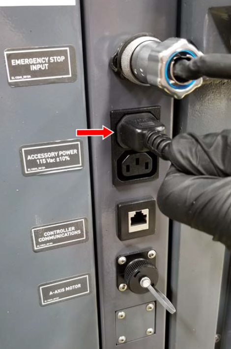
Figure 17: Connecting the monitor cable to the Accessory Power Port.
a. Connect the monitor's power supply into the monitor.
b. Route the power supply down the monitor post.
c. Connect one end of one Controller/Monitor cable (provided in the machine owner's kit) to the loose end of the monitor's power supply.
d. Route the loose end of the Controller/Monitor cable through the square tube arm and toward the electrical cabinet.
e. Connect the loose end of the Controller/Monitor cable into one of the Accessory Power Ports on the front right end of the electrical cabinet.
f. Attach the power supply to the monitor post with one cable tie (provided in the machine owner's kit).
-
Connect the PathPilot controller's power supply to the PathPilot controller.
-
Connect the loose end of the power supply to one of the Controller/Monitor cables provided.
-
Route the power cable down the monitor post, through the square tube arm, and toward the electrical cabinet.
-
Connect the loose end of the Controller/Monitor cable into one of the Accessory Power Ports on the front right end of the electrical cabinet.
-
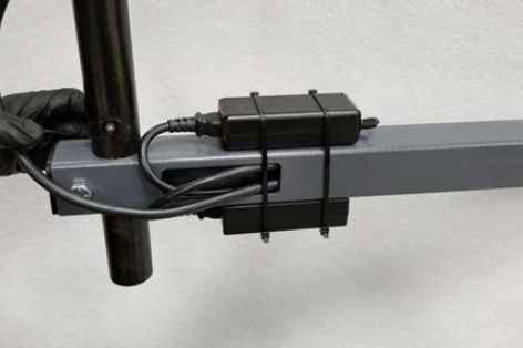
Attach the PathPilot controller and monitor power supplies to the square tube arm with cable ties (provided in the machine owner's kit).
-
Find the Ethernet cable (provided in the machine owner's kit), and then connect it to the Controller Communications outlet on the front right end of the electrical cabinet.
-
Route the loose end of the Ethernet cable toward the PathPilot controller, and then connect it to the PathPilot controller.
-
Secure the operator box cable, Ethernet cable, and power supply cables to the Controller Arm with four wire tie mounts and four cable ties.
Looking for more information?
This is a section of the 24R operator's manual. To view the whole manual, go to Tormach document UM10564.
If you have additional questions, we can help. Create a support ticket with Tormach Technical Support at tormach.com/how-to-submit-a-support-ticket for guidance on how to proceed.