IMPORTANT! Please read this section before you begin installing your Automatic Tool Changer (ATC).
PathPilot You must update your controller to the latest version of PathPilot before installing and operating the ATC. If you don't, there's a risk that the ATC could become inoperable.
Purpose
This document gives instructions on installing and using an Automatic Tool Changer (ATC) for 1100MX.
Product Information
Product: Automatic Tool Changer (ATC) for 1100MX (PN 39289)
The Automatic Tool Changer (ATC) holds up to 12 tools in a single tray. If your program requires more tools, the ATC changes tools automatically for all tools assigned to the tray, and pauses for a manual tool change for all tools not assigned to the tray.
|
Quantity |
Description |
|
1 |
ATC Assembly |
|
3 |
ATC Fixed Standoff Assembly (PN 38492) |
|
10 |
Plastic Screw (PN 32173) |
|
1 |
ATC Tilt Adjust Eccentric Standoff Assembly (PN 38493) |
NOTE: If any items are missing, we can help. Create a support ticket with Tormach Technical Support at tormach.com/how-to-submit-a-support-ticket for guidance on how to proceed.
Before You Begin
-
If there's a tool holder in the spindle, remove it.
-
Remove any accessories or fixtures from the machine table.
-
Center the machine table: from the PathPilot interface, in the MDI Line DRO field, type G20 G53 G1 X9 Y-5.5 Z0 F20. Then select the Enter key.
IMPORTANT! You must update your controller to the latest version of PathPilot before installing and operating the Automatic Tool Changer. If you don't, there's a risk that the ATC could become inoperable. -
Update your controller: From the Status tab, select Update. Then, follow the on-screen instructions. Once the controller is updated to the latest version of PathPilot, go to Step 5.
WARNING! Electrical Shock Hazard: You must power off the machine before making any electrical connections. If you don't, there's a risk of electrocution or shock. -
Power off the machine and the PathPilot controller.
-
Push in the machine's red Emergency Stop button, which removes power to motion control.
-
From the PathPilot interface, select Exit.
-
Turn the Main Disconnect switch to OFF on the side of the electrical cabinet.
-
Setup
Required Tools
This procedure requires the following tools. Collect them before you begin.
-
1-1/2 in. adjustable wrench
-
16 mm and 19 mm open-ended wrench
-
Marker
-
Metric hex wrench set
-
Phillips screwdriver
-
Small, flat-head screwdriver
-
Snips
-
Socket wrench, 13 mm socket, and (optionally) an extender
Required Tools for Verification
-
BT30 tool holder (for alignment rod)
-
Machinist's square, between 6 in. and 9 in. (152 mm and 229 mm)
-
Straight rod (for BT30 tool holder), between 8 in. and 12 in. (203 mm and 305 mm)
Air Requirements
You must verify that the site conforms to the following air supply requirements.
-
Air Pressure Between 90 psi and 120 psi (620 kPa to 825 kPa).
If the air supply is more than 120 psi (825 kPa), you must use a regulator. -
Air Volume For successive back-to-back tool changes, at least 2 cfm at 90 psi is required.
Exact air volume depends on the frequency of tool changes. -
Dry Air We recommend using a compressed air dryer, desiccator, or filter between the air compressor and the machine.
-
Lubricated Air You must lubricate the air with air tool oil.
Use the pre-installed FRL Filter-Regulator-Lubricator for this purpose.
Install the Automatic Tool Changer (ATC)
Complete the following steps in the order listed:
Disassemble the Power Drawbar Button
-
Disconnect the shop air supply from the machine.
-
Remove four M5 × 0.8 - 10 mm button head cap screws that secure the Power Drawbar button cover.
-
Disconnect the air lines from the Retract and Extend ports on the Power Drawbar.
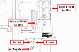
-
Disconnect the air line from the Air Supply port on the Power Drawbar button.
-
Remove two M4 × 0.7 - 50 mm socket head cap screws that secure the Power Drawbar button to the spindle head. Then, cut the cable ties that secure the air lines together.
-
Remove the Power Drawbar button from the spindle head.
Install the Air Cylinder
-
Attach the air cylinder on to the ATC main assembly.
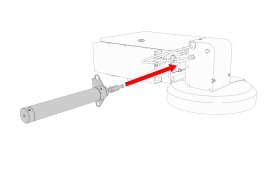
-
Secure the air cylinder to the ATC main assembly with a 12 mm hex wrench (provided) and two M14 × 20 mm socket head cap screws.
-
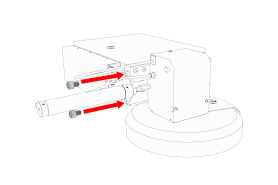
Connect the air lines from the ATC main assembly to the air cylinder as follows:
-
Connect the short air line to the front of the cylinder.
-
Connect the long air line to the back of the cylinder.
-
Mount the Automatic Tool Changer (ATC) Bracket
-
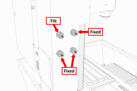
Identify the four provided standoffs that are used to mount the ATC to the Z-column:
-
Three fixed standoffs
-
One tilt standoff
-
-
Remove the flange nuts and the washers from the standoffs, and then set them aside.
-
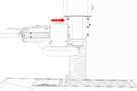
Identify and remove the four set screws on the Z-column with a flat-blade screwdriver.
-
Install the four standoffs on the Z-column as shown in the following image.
-
Securely tighten the standoffs on the Z-column with a 1-1/2 in. adjustable wrench.
-
Put the ATC mounting bracket on the standoff's threaded studs as shown in the following image.
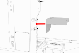
NOTE: Verify that the tilt standoff's eccentric cam fits into the large slot on the ATC mounting bracket.
-
Secure the bracket by reinstalling the washers and flange nuts that you removed in Step 2 with a 13 mm socket.
-
Pull the bracket toward the front of the machine. You'll make adjustments to the location of the bracket later in this procedure, but we recommend starting with it moved forward.
Install the Main Assembly
-
Remove the four preinstalled M8 × 1.25 - 16 mm socket head cap screws and washers from the bottom of the ATC electrical cabinet. Then, set all aside for later use.
CAUTION! Team Lift Required: You must have the aid of more than one person to lift and move the object. The object is heavy, and lifting it by yourself can cause serious injury. -
Lift the ATC main assembly on to the mounting bracket.
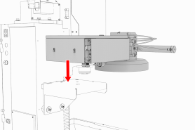
-
Align the locating pin on the ATC main assembly with the matching hole in the mounting bracket.
-
Secure the ATC main assembly to the mounting bracket with the four M8 × 1.25 - 16 mm socket head cap screws and washers that you set aside in Step 1.
Level the Automatic Tool Changer (ATC)
This section gives instructions to roughly level the ATC on the machine by using a long, straight rod. More adjustments are made later in the installation procedure.
NOTICE! After the initial installation, you must level the ATC. If you don't, there's a risk of machine damage.
Complete the following steps in the order listed:
Prepare the Machine
-
Push the tool tray toward the spindle.
-
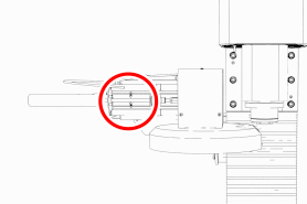
Verify that the linear bearing on the ATC is flush with the ATC main assembly.
-
Find a straight rod between 8 in. and 12 in. (203 mm and 305 mm) long. Verify that it's straight: roll it on a known flat surface (like a granite surface plate).
NOTE: You'll use the rod to verify that the ATC is correctly installed on the mill, so it must be straight. -
Put the alignment rod into a tool holder.
-
Put the tool holder into the fork so that the groove in the tool holder slides into the fork, and so that the drive slot aligns with the dog. Don't rest the tool holder on top of the fork.
-
Put a machinist's square on the machine table.
Examine Perpendicularity in the Y Direction
-
Verify that the rod is perpendicular to the machine table in the Y direction: compare the rod's position to the vertical edge of the machinist's square.
-
If the rod is perpendicular to the vertical edge of the machinist's square, go to "Examine Perpendicularity in the X Direction".
-
If the rod must be adjusted, go to Step 2.
-
-
Loosen the flange nuts on the standoffs.
-
Turn the tilt standoff with an adjustable wrench, and slowly pivot the ATC until the rod is perpendicular to the vertical edge of the machinist's square.
-
Tighten the flange nuts with a 13 mm socket.
-
Reexamine the alignment of the ATC in the Y direction. If the rod isn't perpendicular to the vertical edge of the machinist's square, repeat Steps 2 through 5.
Examine Perpendicularity in the X Direction
-
Verify that the rod is perpendicular to the machine table in the X direction: compare the rod's position to the vertical edge of the machinist's square.
-
If the rod is perpendicular to the vertical edge of the machinist's square, go to "Examine the Alignment of the Carousel Door Opening".
-
If the rod must be adjusted, go to Step 2.
-
-
Loosen the two socket head cap screws on the linear rails.
-
Slowly pivot the linear rails up or down until the rod is perpendicular to the vertical edge of the machinist's square.
-
Tighten the socket head cap screws.
-
Reexamine the alignment of the ATC in the X direction. If the rod isn't perpendicular to the vertical edge of the machinist's square, repeat Steps 2 through 5.
Examine the Alignment of the Carousel Door Opening
-
Remove the tool holder from the fork, and set it aside.
NOTE: You'll need this tool later in the installation procedure to make further alignments. -
Power on the machine and the PathPilot controller.
-
Turn the Main Disconnect switch to ON on the side of the electrical cabinet.
-
Twist out the machine's red Emergency Stop button, which enables movement to the machine axes and the spindle.
-
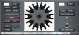
Press the Reset button.
-
Bring the machine out of reset and reference it.
-
-
Verify that the ATC is all the way forward (toward the spindle), and then slowly move the Z-axis down (-Z) to examine the clearance of the carousel door opening.
-
Verify that the carousel door opening is approximately equal to the front back and left of the spindle mounting flange:
-
If the carousel door opening is approximately equal, go to Step 8.
-
b. If the carousel door opening must be adjusted, go to Step 5.
-
Loosen the four socket head cap screws that secure the ATC main assembly to the mounting bracket with a 6 mm hex wrench.

-
Adjust the carousel door opening as required:
-
If the Carousel Door Opening is Contacting the Front Pivot the ATC around the locating pin on the bottom of the mounting bracket toward the front of the machine (closer to you).
-
If the Carousel Door Opening is Contacting the Back Pivot the ATC around the locating pin on the bottom of the mounting bracket toward the back of the machine (closer to the machine column).
-
If the Carousel Door Opening is Contacting the Left Loosen the four flange nuts that attach the mounting bracket to the column to move the bracket forward or backward.
NOTE: Moving the ATC mounting bracket could change the position of the tilt standoff (on the Z-column). If you move it, you must verify that the ATC is still correctly installed; go to "Examine Perpendicularity in the Y Direction".
Repeat this step as needed.
-
-
Tighten the socket head cap screws and the flange nuts (if you loosened them in Step 5).
-
Move the tool tray to its retracted position.
-
Center the machine table: from the PathPilot interface, in the MDI Line DRO field, type G20 G53 G1 X9 Y-5.5 Z0 F20. Then select the Enter key.
-
Power off the machine and the PathPilot controller.
-
Push in the machine's red Emergency Stop button, which removes power to motion control.
-
From the PathPilot interface, select Exit.
-
Turn the Main Disconnect switch to OFF on the side of the electrical cabinet.
-
Make Air Connections
-
Cut the cable tie that secures the ATC cables and plastic tubes together with snips.
-
Route the loose ends of the two 1/4 in. plastic tubes connected to the ATC main assembly through the enclosure knockout, up the energy chain, and toward the Power Drawbar. Then, pull the air line from the FRL back through the energy chain.
WARNING! Crush Hazard: If the ATC isn't completely retracted, it could move once the air is reconnected. When you reconnect the air, you must keep your hands away from the ATC. -
Trim and connect the loose ends of the 1/4 in. plastic tubes in the following order:
-
Connect the Retract (PDB Bottom) airline to the bottom push-to-connect elbow on the Power Drawbar.
-
Connect the Advance (PDB Top) airline to the top push-to-connect elbow on the Power Drawbar
-
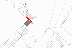
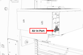
Connect the air supply line from the FRL to the air in port in the ATC main assembly, as shown in the following image.
-
d. If you haven't already done so, connect your shop's air supply to the FRL.
Make Electrical Connections
-
Route the ATC power cable and the USB cable toward the rear of the machine and out of one of the enclosure knockouts.
-
Put the USB cable in the access hole in the rear of the stand toward the controller.
-
Put the USB cable into an open USB port on the PathPilot controller.
IMPORTANT! Do not connect the ATC USB cable to a USB hub. Make the connection directly to the PathPilot controller itself. If you don't have any free USB ports on the controller, connect a different accessory to a USB hub. -
Connect the ATC power cable to the ATC Power connector on the side of the electrical cabinet (below the Enclosure Lights Power connectors).
Verify the Installation
-
Power on the machine and the PathPilot controller.
-
Turn the Main Disconnect switch to ON on the side of the electrical cabinet.
-
Twist out the machine's red Emergency Stop button, which enables movement to the machine axes and the spindle.
-
Press the Reset button.
-
Bring the machine out of reset and reference it.
IMPORTANT! You must update your controller to the latest version of PathPilot before operating the Automatic Tool Changer. If you don't, there's a risk that the ATC could become inoperable.
-
-
If you have not yet done so, you must make sure that the PathPilot controller is updated to the latest version of PathPilot: From the Status tab, select Update. Then, follow the on-screen instructions.
-
From the PathPilot interface, on the Settings tab, select the ATC radio button.
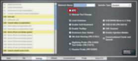
The ATC tab appears in the PathPilot interface.
NOTE: If prompted, you may need to update the firmware for the ATC. Follow the on-screen instructions.
-
Load a tool into the spindle:
-
Push and hold the drawbar open button on the side of the ATC.
-
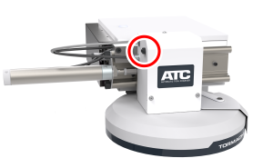
The drawbar opens.
b. Load a tool into the spindle.
c. Release the button.
The drawbar closes.
-
From the PathPilot interface, on the Main tab, in the RPM DRO field, type 1000. Then select the Enter key.
-
Select FWD.
The spindle starts. -
From the Status tab, make sure that the VFD Running green light comes on.
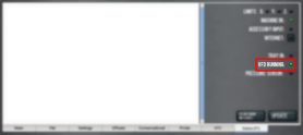
NOTE: If the VFD Running light did not come on in the previous step, we can help. Create a support ticket with Tormach Technical Support at tormach.com/how-to-submit-a-support-ticket for guidance on how to proceed.
-
Select Stop.
The spindle stops.
Make Final Alignments to the Automatic Tool Changer (ATC)
Complete the following steps in the order listed:
Alignment
In this section, you'll adjust the tool alignment and set the tool tray height and encoder position.
-
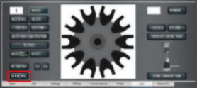
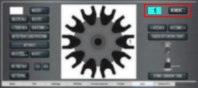
From the PathPilot interface, on the ATC tab, select Ref Tool Tray.
The tool tray spins.
NOTE: You're only required to reference the tool tray once, unlike the mill axes’ referencing procedure.
-
If you haven't already done so, load a tool into the spindle.
-
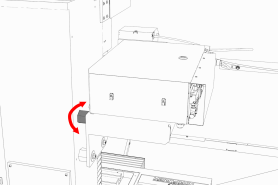
Manually rotate the spindle two revolutions by hand.
The encoder has now been oriented. -
Disconnect the air from the machine.
-
While manually advancing the tool tray toward the spindle, align the fork with the tool. Complete the following steps in the order listed:
-
Slowly jog the Z-axis up or down until the groove in the fork aligns with the groove in the tool holder.
-
Determine if the tray must move clockwise or counterclockwise to align the fork with the tool holder. From the PathPilot interface, in the ATC tab, either select -- to step the tool tray counterclockwise or ++ to step the tool tray clockwise.
-
Fully seat the ATC to its tray load position, verifying that the tool and its drive dog slots are fully inserted into the fork.
-
-
Verify that, from the Status tab, the ATC Tray In LED is still illuminated.
If the LED isn't illuminated, examine the tool tray. It may have exceeded the Tray In sensor during adjustments in the previous step. -
On the ATC tab, select Set TC POS.
The tool change position has now been set.
-
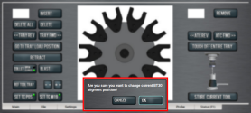
Select Set TC M19. Then, in the dialog box that displays, select OK.
-
Follow the on-screen instructions to set the spindle's tool change rotation position:
-
Rotate the spindle clockwise in the fork by hand. Then, select OK.
-
Rotate the spindle counterclockwise in the fork by hand. Then, select OK.
The tool change rotation position has now been set. In the dialog box that displays, select OK.
-
-
Manually move the ATC back to the retracted position.
WARNING! Crush Hazard: If the ATC isn't completely retracted, it could move once the air is reconnected. When you reconnect the air, you must keep your hands away from the ATC. -
Reconnect the air.
-
Remove the tool from the spindle.
-
Move the Z-axis up: in the MDI Line DRO field, type G20 G53 G1 Z0 F20. Then select the Enter key.
-
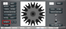
On the ATC tab, select Go To Tray Load Position. Then, manually load a tool into the fork.
-
Orient the spindle: from the PathPilot interface, in the MDI Line DRO field, type M19 R0 Q10. Then select the Enter key.
-
Open the drawbar: on the ATC tab, select Collet, and wait until the LED toggles from Closed to Open.
NOTE: You must verify that the drawbar is open (and not just that the brake is engaged) before you continue. -
Verify that the spindle is concentric with the tool: slowly jog the Z-axis down and, depending on the result, do one of the following:
-
If the Spindle is Concentric with the Tool You've completed the alignments.
-
If Adjustments are Required Go to Step 18.
-
-
Determine if the tray must move left or right. Use two wrenches to loosen the jam nut on the end of the cylinder rod, making sure that you don't spin the rod end when adjusting the jam nut. Then, either turn the rod end one-half turn further on to the cylinder rod to move the tool tray to the left, or turn it one-half turn off of the cylinder rod to move the tool tray to the right. Once finished, tighten the jam nut.
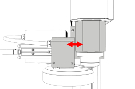
NOTE: Don't move the tool tray more than 0.100 in. in either direction (left or right). If you do, the tool tray will exceed the Tray In sensor, which affects how ATC operations are communicated to PathPilot.
-
Adjust for the ATC's backlash: apply light pressure forward and backward on the carousel; then, from the PathPilot interface, on the ATC tab, select ++ or -- until there's equal space on the front and the back of the BT30 taper.
-
Verify that, from the Status tab, the ATC Tray In LED is still illuminated.
If the LED isn't illuminated, examine the tool tray. It may have exceeded the Tray In sensor during adjustments in the previous step. -
Repeat adjustments until the tool's shank is concentric with the spindle.
-
Move the Z-axis up: in the MDI Line DRO field, type G20 G53 G1 Z0 F20. Then select the Enter key.
-
Remove the tool from the ATC. Then, select Retract.
Operation
NOTE: You must always have a tool holder in the drawbar while the machine is not in use. Retracting the Power Drawbar to the clamped position with no tool holder in the drawbar will eventually fatigue the drawbar, and may shorten its service life. For more information, refer to the Power Drawbar documentation.
Read the following sections to understand how to operate the ATC:
Assign Tool Numbers
Use any tool number, from 1-1000, to assign a position in the tool tray.
Automatically Load a Tool into the Tool Tray
-
Load a tool into the spindle.
-
From the PathPilot interface, on the ATC tab, type the tool number in the Tool DRO field. Then select the Enter key.
-
Select Store Current Tool.
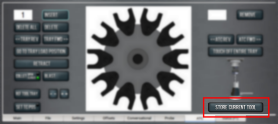
The tool is assigned to the nearest open slot. The ATC fetches the tool from the spindle and stores the tool in the tray. When stored, the tool number displays on the tray image in the center of the screen.
-
Click Retract.
The tray returns to the machining position.
Automatically Unload a Tool From the Tool Tray
NOTE: Typing a new tool number in the Tool DRO field doesn't remove the tool from its tray assignment.
-
From the PathPilot interface, on the ATC tab, type the tool number in the Remove DRO field. Then select the Enter key.
-
Select Remove.
The ATC fetches the tool from the tray. -
Unload the tool from the spindle.
-
From the ATC tab, select ATC FWD or ATC REV.
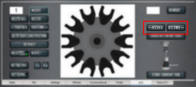
The tray moves to the next location and fetches another tool.
-
Select Retract.
The tray returns to the machining position.
Load a Tool into the Spindle
Load a tool into the spindle:
-
Push and hold the drawbar open button on the side of the ATC.

The drawbar opens.
-
Load a tool into the spindle.
-
Release the button.
The drawbar closes.
Manually Unload a Tool From the Tool Tray
-
From the PathPilot interface, on the ATC tab, in the Insert DRO field, type the tool number. Then select the Enter key.
-
Select Go To Tray Load Position.
The spindle head moves up and the ATC moves into the door open position. -
Select Delete.
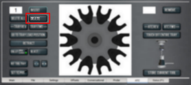
The tool is unassigned from the tray and the tray moves to that tool.
-
Select Tray FWD or Tray REV.
The tray moves to the next slot location. -
Select Retract.
The tray returns to the machining position.
Retrieve a Tool From the Tool Tray
-
Depending on your workflow, do one of the following from the PathPilot interface:
-
Type the command directly into the MDI Line DRO field using the following format: T[TOOL NUMBER] M06
For example, T1 M06
-
-
Type the tool number in the Tool DRO field. Then select the Enter key.
Switch to Manual Tool Changes
-
From the PathPilot interface, on the Settings tab, select the Manual Tool Change radio button.
The Automatic Tool Changer (ATC) is prevented from making tool changes.
Troubleshooting
If you're having issues with the ATC, read the following sections:
Spindle Rotates on Contact, or Spindle Isn't Rigidly Clamped
|
Cause: Insufficient shop air pressure. |
|
|
Probability |
How-To Steps |
|
High |
|
|
Cause: Excessive torque on spindle. |
|
|
Probability |
How-To Steps |
|
High |
|
|
Cause: Main machine FRL’s setpoint too low. |
|
|
Probability |
How-To Steps |
|
Medium |
|
|
Cause: ATC Low Pressure Regulator setpoint too low; Clogged or damaged ATC Low Pressure Regulator. |
|
|
Probability |
How-To Steps |
|
Medium |
|
Schematic
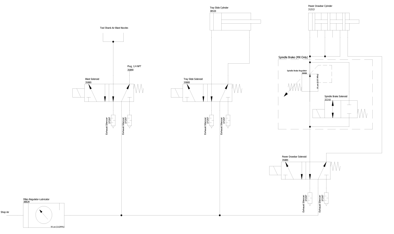
To view a PDF version of your manual, go to Tormach document TD10626.
If you have additional questions, we can help. Create a support ticket with Tormach Technical Support at tormach.com/how-to-submit-a-support-ticket for guidance on how to proceed.