Purpose
This document gives instructions on installing the Lube Cube Coolant Kit on the following Tormach mills:
-
1100M
-
1100MX
-
770M
-
770MX (sold before December 2025, with serial numbers beginning with MF)
IMPORTANT! This kit isn't compatible with 770MX mills sold after December 2025 (with serial numbers beginning with ML). -
PCNC 1100
-
PCNC 770
-
PCNC 440
Product Information
Product:
Installation
Required Items and Tools
-
5 mm hex wrench
-
11 mm wrench
-
15 mm wrench
-
Phillips screwdriver
-
Snips
-
Thread seal tape
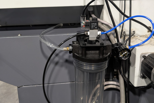
Assemble the Lube Cube
-
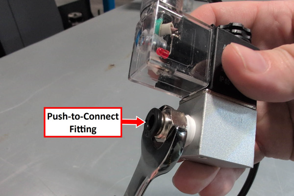
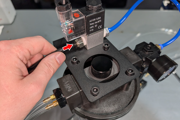
Apply thread seal tape to the 1/4 in. NPT push-to-connect fitting, and then install it into the solenoid using a 15 mm wrench.
-
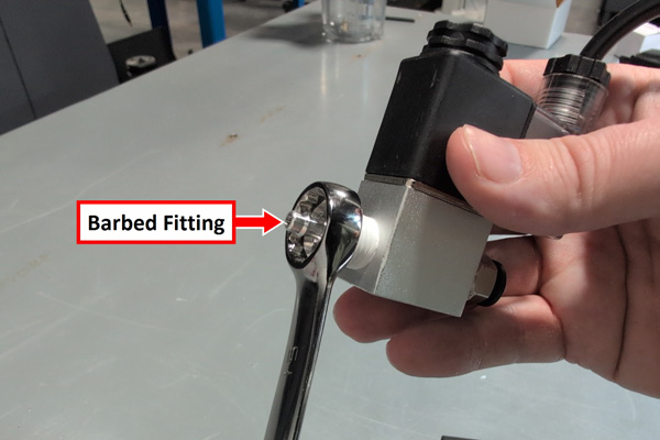
Apply thread seal tape to the 1/4 in. NPT barbed fitting, and then install it into the solenoid using a 15 mm wrench.
-
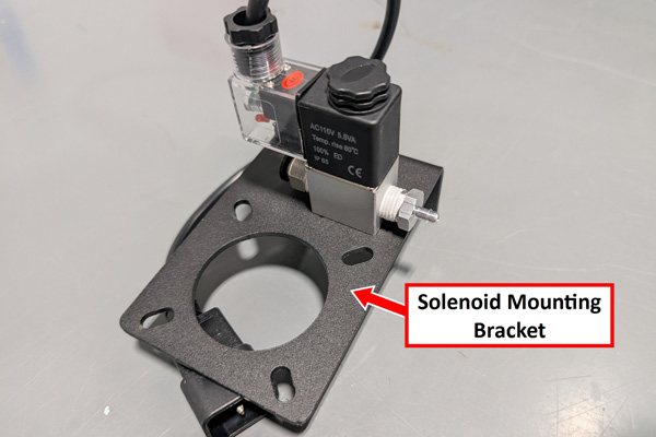
Install the solenoid onto the solenoid mounting bracket with two M4 × 5 mm Phillips head screws using a screwdriver.
-
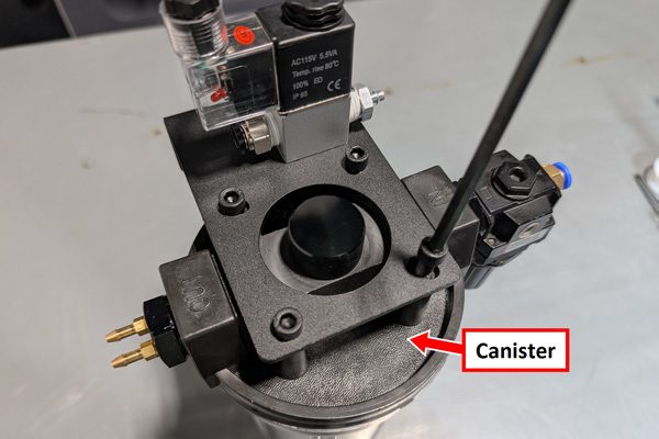
Mount the solenoid and bracket assembly onto the top of the canister with four M6 socket head cap screws using a 5 mm hex wrench. Make sure that the barbed fitting is pointed towards the pressure regulator.
-
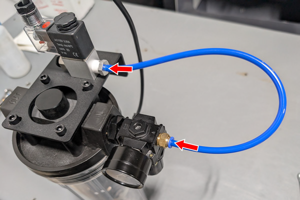
Apply thread sealant tape to the threads of the pressure gauge, and then install it into the air pressure regulator using an 11 mm wrench.

-
Install one end of the short blue tubing into the pressure regulator and the other end of the tubing onto the barbed fitting on the solenoid.
-
Prepare the duplex tubing:
-
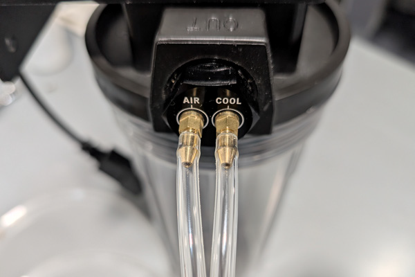
Split the tubes apart on one end and connect them to the barbed outlet fittings on the canister.
-
On the opposite end, separate the tubes approximately 5 in. back from the end.
-
Identify which tube connects to the canister fitting labeled Cool. Trace that tube to the loose end and cut approximately 3 in. from the end. Set aside the removed section.
-
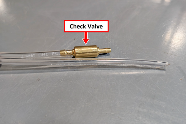
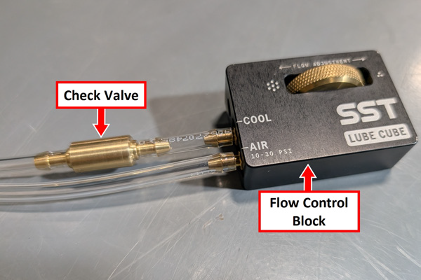
Install the brass check valve onto the tube connected to the Cool fitting. Make sure that the arrow on the valve points away from the canister.
-
Install the removed tubing section onto the other end of the check valve.
-
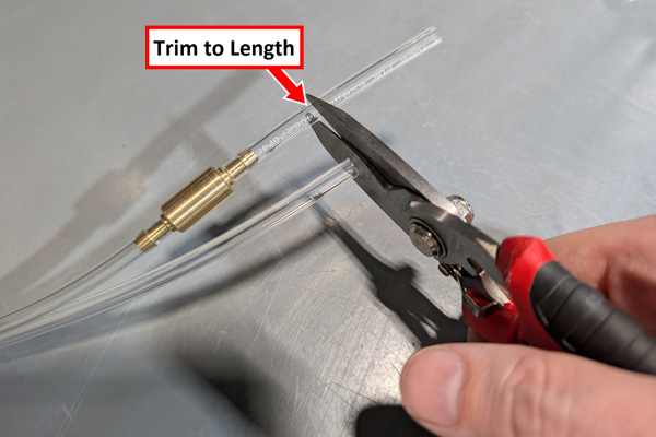
Trim the longer of the two tubes so that both tubes are equal in length.
-
Connect the duplex tubing to the flow control block. The tube with the check valve connects to the barbed fitting labeled Cool.
-
Install the spray nozzle into the flow control block.
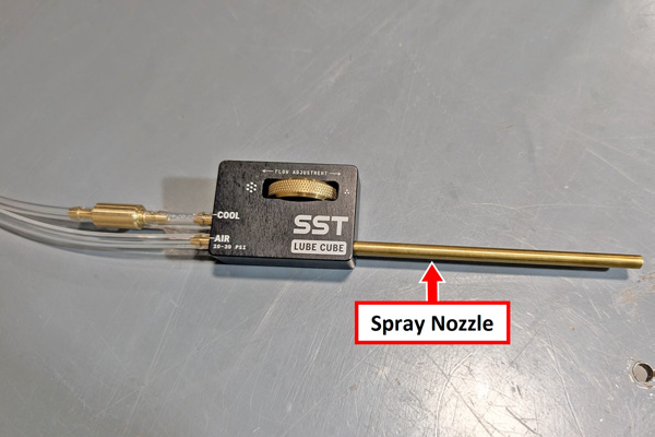
NOTE: Thread seal tape isn't required because this port is sealed.
-
Connect one end of the 1/4 in. black polyurethane tubing into the push-to-connect fitting on the solenoid valve.
-
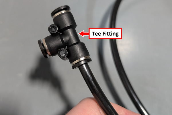
Install the push-to-connect tee fitting onto the loose end of the 1/4 in. black tubing.
-
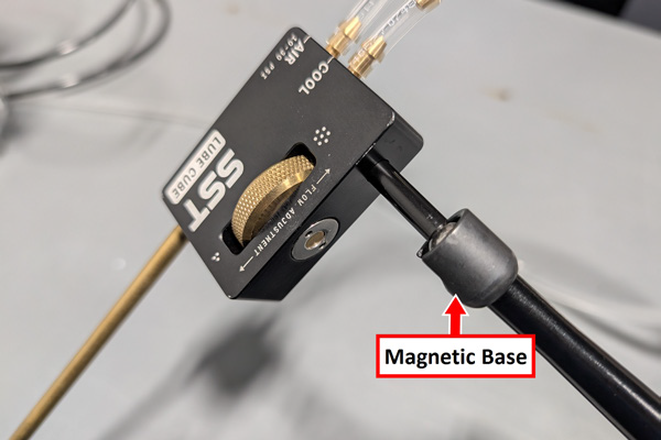
Thread the magnetic base into the bottom of the flow control block.
-
You've completed the assembly of the Lube Cube. Go to "Install the Lube Cube on the Machine".
Install the Lube Cube on the Machine
Depending on which machine you're installing the Lube Cube on, the installation varies.
1100M, 1100MX, 770M, and 770MX (MF Serial Number) Mills
IMPORTANT! This kit isn't compatible with 770MX mills sold after December 2025 (with serial numbers beginning with ML).
-
On the back of the chip pan below the electrical cabinet, locate the two threaded M5 holes. Mount the canister to the chip pan using two M5 button head cap screws.
-
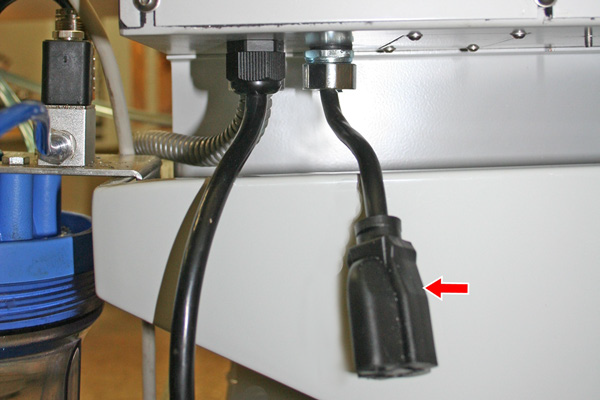
Route the solenoid power cable to the outside of the electrical cabinet, and connect it to the Coolant Pump Power outlet.
-
Unthread the magnetic base from the bottom of the flow control block. Then, route the flow control block underneath the electrical cabinet and into the enclosure.
-
Reinstall the threaded magnetic base into the flow control block.
-
Mount the flow control block to the machine table or the spindle head sheet metal using the magnetic base.
-
You've completed the installation of the Lube Cube on your machine. Go to "Make Air Connections".
PCNC 440 Mills
-
Hang the canister onto the back of the chip pan using the solenoid mounting bracket.
-
Route the loose end of the solenoid power cable to the electrical cabinet, and plug it into the cord end.
-
Route the flow control block and the magnetic base underneath the electrical cabinet and into the enclosure.
-
Mount the flow control block to the machine table or the spindle head sheet metal using the magnetic base.
-
You've completed the installation of the Lube Cube on your machine. Go to "Make Air Connections".
PCNC 1100 and PCNC 770 Mills
-
Hang the canister onto the back of the chip pan using the solenoid mounting bracket.
-
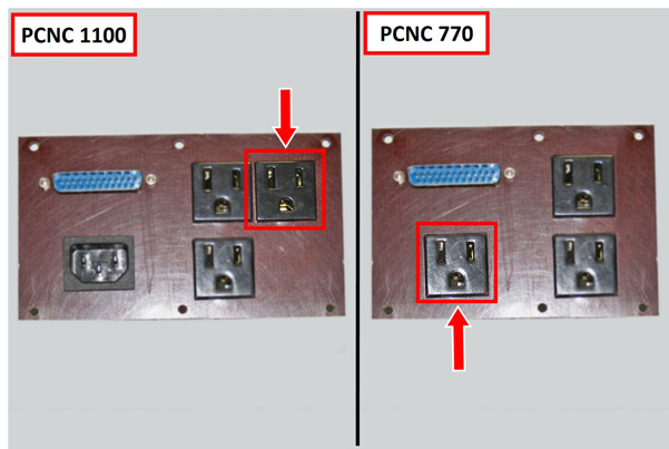
Route the loose end of the solenoid power cable to the power connection panel (under the electrical cabinet), and plug it into the Coolant outlet.
-
Route the flow control block and the magnetic base underneath the electrical cabinet and into the enclosure.
-
Mount the flow control block to the machine table or the spindle head sheet metal using the magnetic base.
-
You've completed the installation of the Lube Cube on your machine. Go to "Make Air Connections".
Make Air Connections
NOTE: The Lube Cube is designed to operate at high volume and low pressure (10–30 psi), consuming approximately 0.7–2.0 cfm.
-
Locate the air supply line from your compressor.
-
Use the tee fitting installed on the 1/4 in. black tubing to splice into the air supply line.
To view a PDF version of your manual, go to Tormach document TD10879.
If you have additional questions, we can help. Create a support ticket with Tormach Technical Support at tormach.com/how-to-submit-a-support-ticket for guidance on how to proceed.