Background
The spindle is the rotating assembly that holds the tool/tool holder. It’s powered by a motor that can either be integral or – like most of our machines – external, relying on a belt and pullies to transmit the power.
The VFD that controls the motor doesn't power on with the machine. Instead, it turns on after you command the spindle to start.
Tools
-
Multimeter
-
Adjustable Wrench
-
Screwdriver set
Disconnect the J3 (if applicable)
Reason: Bad switch or potentiometer.
The J3 connects the Manual Operator Panel to the Machine Control Board. By disconnecting it, it puts the MCB into auto mode and eliminates any issues that could be caused to a bad switch or potentiometer. (This only applies to PCNC machines with the Operator Panel on the electrical cabinet door.)
Verify Speed was Commanded Properly
Reason: Commanded speed did not execute.
To command a specific RPM in PathPilot, you enter your desired speed, and then you MUST press Enter for the machine to accept the commanded speed. Then proceed to hit FWD or REV.
Inspect and/or Re-tension the Belt
Reason: The belt is loose, worn, or damaged.
-
Open the spindle motor door and visually inspect the belt to ensure there is not excessive wear or damage.
-
Firmly push the spindle belt between the pulleys. If it is properly tensioned, the spindle belt should move between 3 mm (0.125 in.) and 6 mm (0.25 in.). If it's not properly tensioned, continue with the following steps.
-
Unclamp the motor mounting plate: Loosen the clamp handle.
This allows the spindle motor plate to pivot. -
Tighten the spindle belt: Push the pivot handle backward (toward the machine column).
-
Secure the motor mounting plate: Tighten the clamp handle.
-
Firmly push the spindle belt between the pulleys. If it is properly tensioned, the spindle belt should move between 3 mm (0.125 in.) and 6 mm (0.25 in.). If it's not properly tensioned, repeat Steps 3 through 5.
-
Close the spindle motor door.
The Variable Frequency Drive (VFD) isn’t Getting Power
Examine the spindle door and its switch
Reason: The door is open or the switch is malfunctioning.
-
Examine the spindle cover door to verify that it’s closed, being held closed, and the switch is being depressed.
-
If your mill is equipped with door safety switches, make sure your enclosure doors are closed.
Verify that the Spindle Run/Start is Working
Reason: The spindle start signal from the control board isn’t working.
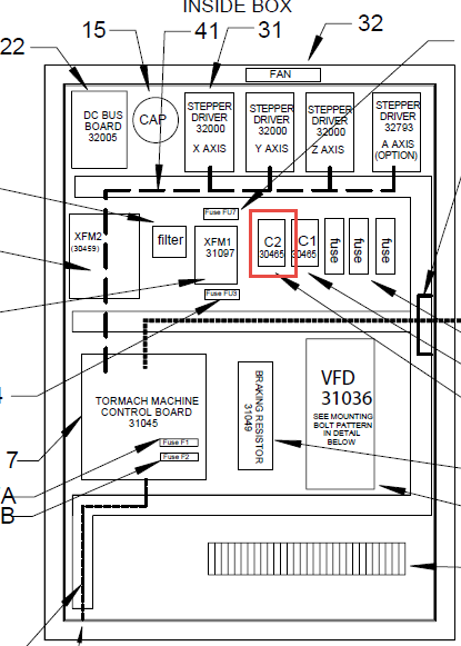
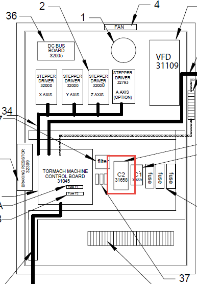
Manually Latch the C2
Reason: C2 is not latching or staying latched
-
Locate the C2 Contactor and remove the cover by sliding it up. You should be able to identify either a dark blue or orange “button” in the center. Press the “button” and note the result.
|
PCNC1100 |
PCNC770 |
|---|---|
|
|
-
If the C2 doesn’t stay latched, this indicates that either is an open circuit up stream of the C2 (spindle door, PDB (if applicable), spindle lock key) or the C2 is faulty.
-
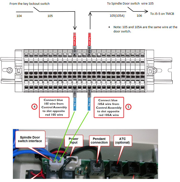
Inspect that the spindle door and spindle lock key are not in an open position.
-
At the C2, measure between wire 106 and 100 for 120 VAC. Then, progress to the 107 to 100. If you read 0 Vac start to work your way back starting with the primary side of the door switch (105a to 100); then the primary side of the power drawbar (105 and 100); and finally the primary side of the spindle lock out (104 to 100). Doing this method you should discover the culprit.
-
c. Test the C2 by jumping wire 106 to wire 107 at the Machine Control Board. As long as you confirmed there was 120 VAC at wire 106, you now should see the coil immediately energize and latch. If not, the wires are disconnect or the C2 is faulty.
NOTE: Jumper wires should only be used for testing purposes.
-
If the C2 Latches, this indicates that the signal to start the spindle isn’t making it to the C2. Using either an analog multimeter or general purpose you tester you can test wire 107 to 100 while commanding a spindle start. This can be very difficult to capture, but you should see a blip on your tests. If there is not a blip you should inspect the communication line to ensure the signal is making its way to the Machine Control Board.
Verify that the VFD is Getting Power
Reason: The VFD is defective.
-
Using a multimeter, confirm you have power getting to the VFD between L1 and L3.
-
If there is power but nothing on the display, contact Tormach Technical Support.
-
If there is no power, review the previous solutions to try and re-establish power.
-
-
If there is a trip or error code that does not clear after power cycling the machine, contact Tormach Technical Support.
Measure the Motor Resistance (Ω)
Reason: The motor has an internal short and is malfunctioning.
-
Power off the machine.
-
Wait 30 seconds, and then remove the U, V, and W wires from the VFD terminals.
-
Measure the resistance between the following wires to see if it is approximately 2-4 Ω:
-
Wires U and V
-
Wires U and W
-
Wires V and W
-
-
Measure the resistance between the following wires to verify that it is >1M Ω or OL, indicating that there is no short:
-
Wire U and Ground (bare exposed metal or a green and yellow wire with a PE label)
-
Wire V and Ground (bare exposed metal or a green and yellow wire with a PE label)
-
Wire W and Ground (bare exposed metal or a green and yellow wire with a PE label)
-
-
Numbers outside of the specified range indicate that the motor or its wiring is bad and needs to be replaced. Perform the same test on the motor cable connector, if applicable.
Identify the VFD Code and Solution
Reason: The VFD is tripped and showing an error.
|
Trip Code |
Condition |
Likely Cause |
|---|---|---|
|
boot |
Boot from SD card. |
Displayed for first 5-6 seconds after power up when booting from SD card. (M200/C200 only) |
|
UU |
DC-BUS under-voltage. |
This happens when the VFD is powered down or loses power. |
|
OU |
DC-BUS over-voltage. |
Braking resistor failed open or wiring connection open between the VFD and the resistor. Resistance to measure 70 ohms. |
|
OI.AC |
VFD output instantaneous over current. |
Phase-to-phase or phase-to-ground short on output of VFD to motor. This trip code cannot be reset until 10 seconds after the trip was initiated. |
|
OI.br |
Braking resistor instantaneous over current. |
Braking resistor shorted or partially shorted out or short in wiring between the VFD and the resistor. Resistance to measure 70 ohms. Check brake resistor wiring. |
|
It.br |
I2t (power) on braking resistor. |
Excessive braking resistor energy caused by too frequent and too severe deceleration cycles or AC supply voltage too high. |
|
It.AC |
I2t (power) on VFD output current (used to
|
Spindle motor is working too hard. Ensure that the spindle is not jammed or sticking. Consider running the spindle motor at half speed for 10 minutes with no load to cool the motor down. |
|
Oht.C |
VFD is working too hard and stops to cool power electronics down to prevent failure. |
Spindle motor is working too hard. Stop running the spindle but leave the VFD power on and let the power electronics cool down. |
|
Oht.I |
Heat sink temperature is too high because the VFD is working too hard and stops to cool power electronics down to prevent failure. Cabinet may also be too hot. |
Spindle motor is working too hard or it is too hot in work location. Stop running the spindle but leave the VFD power on and let the power electronics cool
|
|
HF01 through HF23 |
Hardware fault. |
Failed drive. |