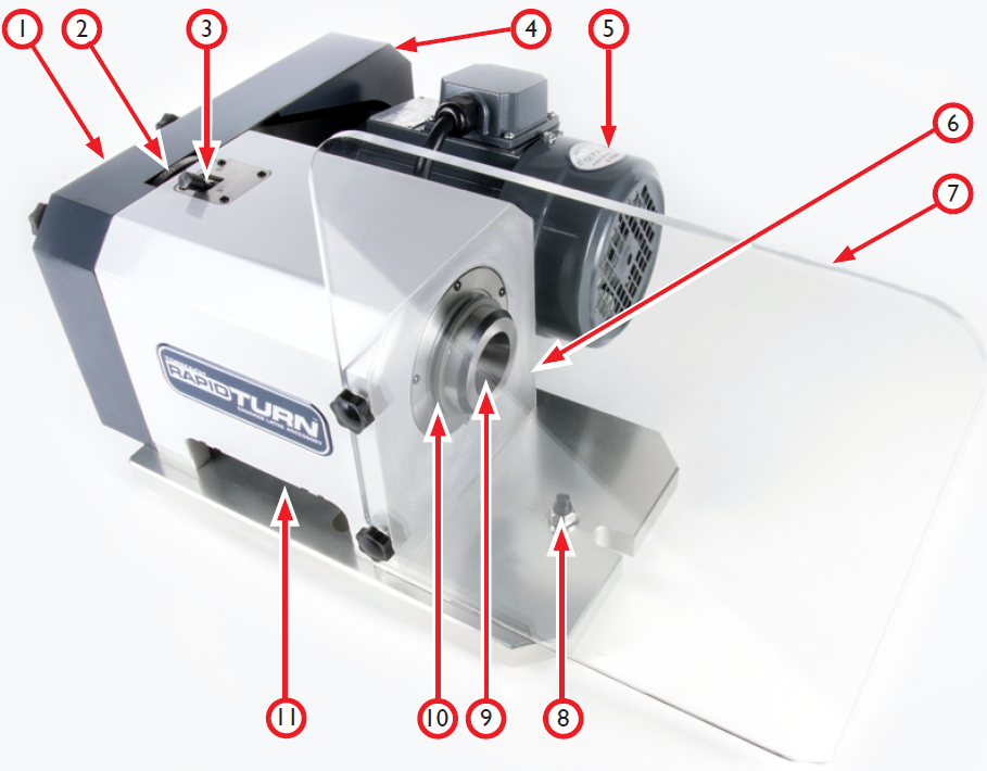
Overview
The Rapidturn is intended for use on the 1100 M/MX, PCNC 1100, 770 M/MX (MF/MH Serials) and PCNC 770.
|
Component |
|
|---|---|
|
1 |
Draw Tube Assembly (not shown) |
|
2 |
Index Plate |
|
3 |
Spindle Lock |
|
4 |
Belt Guard |
|
5 |
Spindle Motor |
|
6 |
Serial Number Plate |
|
7 |
Chip Guard |
|
8 |
Eccentric Alignment Pin |
|
9 |
5C Spindle |
|
10 |
Spindle Seal |
|
11 |
Spindle Speed Sensor (not shown) |
Specifications
Mechanical
|
Key Dimensions |
Swing-over Base Plate |
6” Maximum |
|
|
Weight |
60 lbs. |
|
|
Footprint |
16.25” W x 13.75” L x 9.5” H |
|
Spindle |
Spindle HP |
1 HP continuous |
|
|
Spindle Design |
Native 5C Taper |
|
|
Spindle Speed Range |
Low Belt: 180-2000 RPM High Belt: 300-3500 RPM |
|
|
Tool Holding |
Spindle nose clamp with quick change tool post |
|
Feed Rates |
Rapid Speeds |
90 IPM X-Axis 110 IPM Z-Axis |
|
Temperature |
Operating Range |
55-100° F (12-38° C) |
Electrical
|
Connections |
Spindle Motor connects to mill’s VFD using Quick Change Motor Connection Kit Spindle index sensor connects to mill’s accessory port |
Installation
Required Tools
This procedure requires the following tools. Collect them before you begin.
-
3/4 in. wrench
-
6 mm, 13 mm, 17 mm, and 19 mm wrench
-
8 mm hex wrench
-
Adjustable wrench
-
Dead-blow hammer
-
Machinist stone (or similar)
-
Tin snips
Receiving, Partial Uncrating, and Initial Inspection
Caution! Transport and Lift Hazard: The transport, lifting, and moving of the RapidTurn should be done by qualified professionals. Failure to do so could result in serious injury and/or machine damage.
Shipment Arrival
Depending on products and options ordered, the RapidTurn system arrives in one or more shipments:
-
RapidTurn (freight)
-
Accessory shipment (freight or parcel service, depending on size)
Partial Uncrating
Caution! Sharp Objects: Be sure to wear gloves when uncrating RapidTurn. Failure to do so could result in serious injury.
-
Using tin snips, remove top of crate from shipping pallet.
-
Locate and retain certificate of inspection/packing list.
Shipment Damage or Shortages
Once received, inspect and note any shipping damage that may have occurred during transit. Also check received goods against packing list; any damage claims or shortages must be addressed within 30 days of receipt.
Install the Quick-Change Motor Connection Kit (PCNC Only)
The RapidTurn’s spindle motor is driven by the mill’s spindle motor variable frequency drive (VFD). The Quick-Change Motor Connection Kit (PN 35167) simplifies switching between PCNC mills and the RapidTurn. Refer to TD10370 for instructions on installation and use.
NOTE: The Quick-Change Motor Connection Kit is not required to use the RapidTurn with M/MX mills.
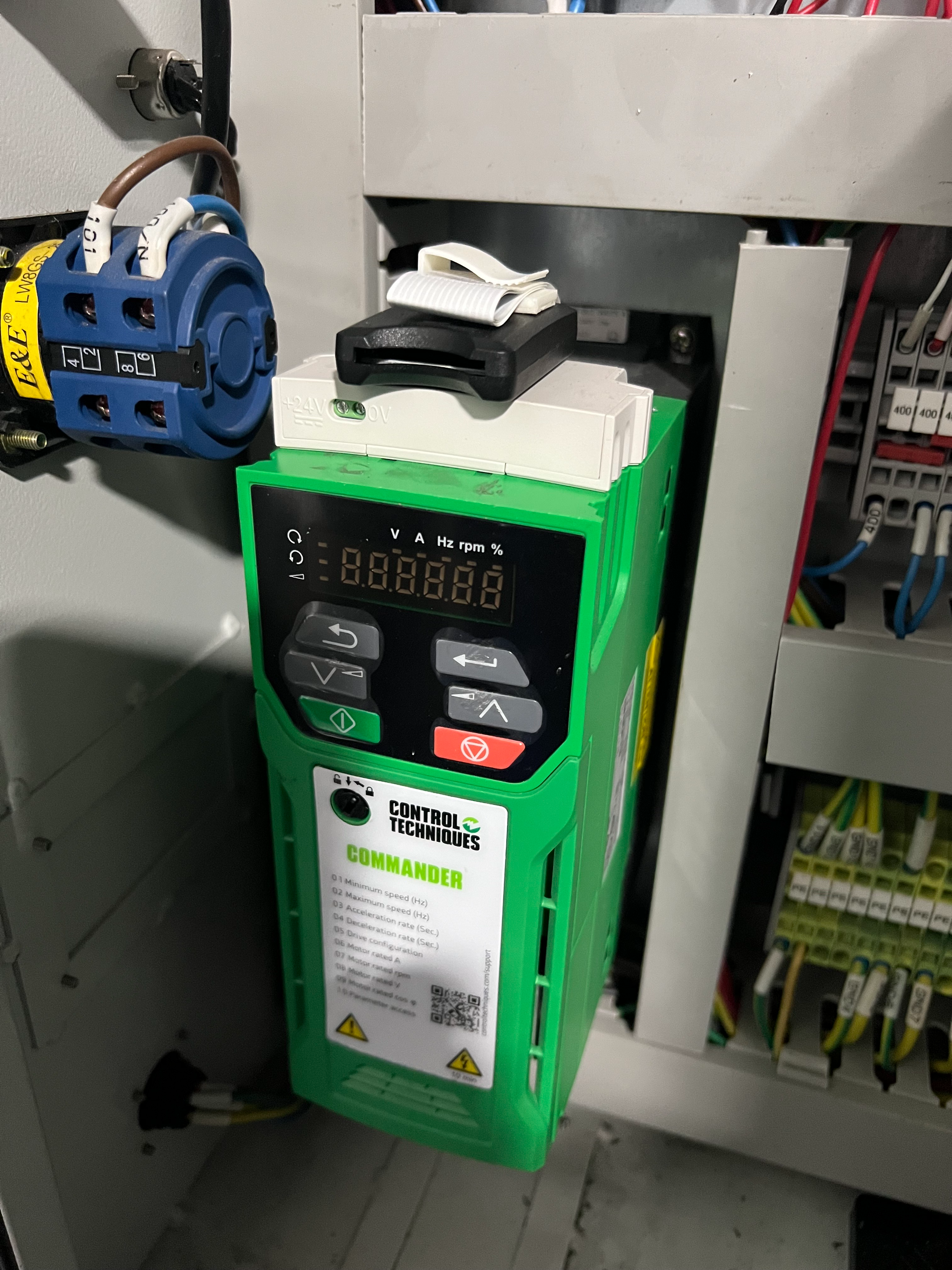
Program the VFD (1100M and PCNC 1100 Only)
If using RapidTurn with certain 1100M mills or all PCNC 1100 mills, a VFD programming stick is required to correctly program the VFD for operation. The correct programming stick varies depending on your machine:
-
1100M SN MA10324 and Below: 1100M RapidTurn Programming Kit (PN 39026)
-
1100M SN MA10325 - MA10629: 1100M RapidTurn Programming Kit (PN 50613)
-
PCNC 1100: VFD Programming Stick Set (PN 37174)
-
If your VFD has been replaced with a C200 Nidec VFD, the programming kit may no longer be needed. Contact Tormach Technical Support to confirm.
NOTE: Using RapidTurn with an 1100MX, any 770, or 1100M SN 10630 and above does not require reprogramming of the VFD.
-
Identify VFD Programming Stick Set; two sticks are included:
-
RapidTurn
-
Mill Spindle
-
Power off mill according to ‘Power Off/On Procedure' detailed below.
Warning! Electrical Shock Hazard: Be sure to power off machine before making any electrical modifications. Failure to do so could results in serious injury or death.
|
Power Off/On Procedure |
||
|
Power Off |
|
|
|
||
|
||
|
Power On |
|
|
|
||
|
||
|
||
IMPORTANT! Ensure the mill is off before inserting RapidTurn VFD Programming Stick.
-
Insert the RapidTurn Programming Stick or SD Card into your VFD.
-
Leave the RapidTurn VFD Programming Stick or SD Card plugged into the VFD during RapidTurn operation.
NOTE: To switch back to mill operation, follow the steps in this section using the included Mill Spindle Stick or SD Card.
Basic Installation Procedure
CAUTION! Collision Hazard: Any tooling, workpiece, workholding device, fixture, or accessory installed within the machine envelope presents a collision hazard during operation. Do not operate before carefully proving out part programs. Failure to do so could result in machine damage.
Setup PathPilot Controller
WARNING! Unattended Operation: Machine is not designed to operate unattended. Do not leave machine unattended during operation. When machine is not in use, turn the main disconnect off. Failure to do so could result in death, serious injury, and/or machine damage.
-
Power on mill according to ‘Power Off/On Procedure' detailed earlier.
-
In the PathPilot interface, click Manual Tool Change on the Settings tab.
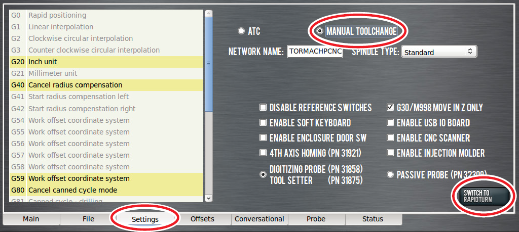
IMPORTANT! Automatic Tool Changer (ATC) cannot be used with Universal Spindle Arm installed on spindle nose. Do not operate mill equipped with an ATC before removing Universal Spindle Arm. Failure to do so could result in machine damage.
-
Click Switch to RapidTurn. This closes mill’s PathPilot interface and opens RapidTurn’s PathPilot Interface. For more information on switching from mill operation to RapidTurn operation, refer to ‘Operation’.
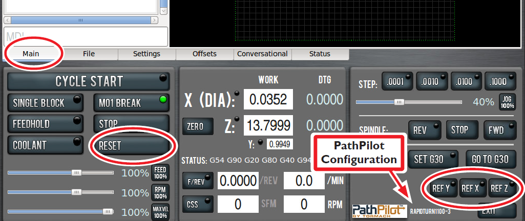
NOTE: The PathPilot machine configuration is listed on the bottom of the screen (see Figure 3). Refer to this before operating to confirm correct configuration is selected.
WARNING! Motion Direction Hazard: Lathe axis orientation and motion direction differs from a mill. Do not operate RapidTurn before becoming familiar with controls. Failure to do so could result in death, serious injury, and/or machine damage.
-
Ensure machine table is free from obstructions.
-
On Main tab, click flashing Reset button.
-
Reference mill by clicking Ref X, followed by Ref Y and Ref Z.
Uncrate
This procedure separates the RapidTurn motor from its base plate to facilitate lifting on the machine table and installation.
-
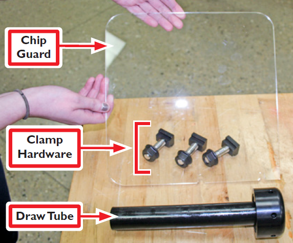
Remove Chip, Clamp Hardware (three flange nuts, three threaded studs, and three T-nuts), and Draw Tube from pallet (see Figure 4); set aside.
-
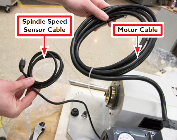
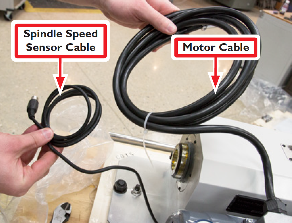
Remove Spindle Speed Sensor Cable and Motor Cable packaging; cut cable ties (see Figure 5).
-
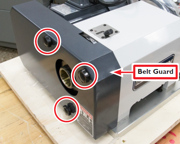
Remove three thumbscrews securing Belt Guard to RapidTurn (see Figure 6); remove Belt Guard and set all aside.
-
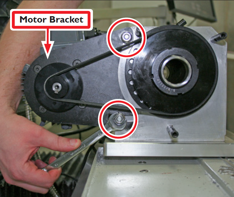
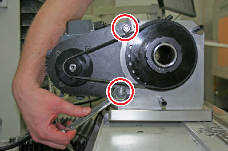
Using a 13 mm wrench, remove two M8 flange nuts securing Motor Bracket to RapidTurn (see figure 7); set aside.
-
Spindle belt slackens when M8 flange nuts are removed; remove belt and set aside.
-
Slide motor sideways off of two Motor Mount Studs (see Figure 8); set aside.
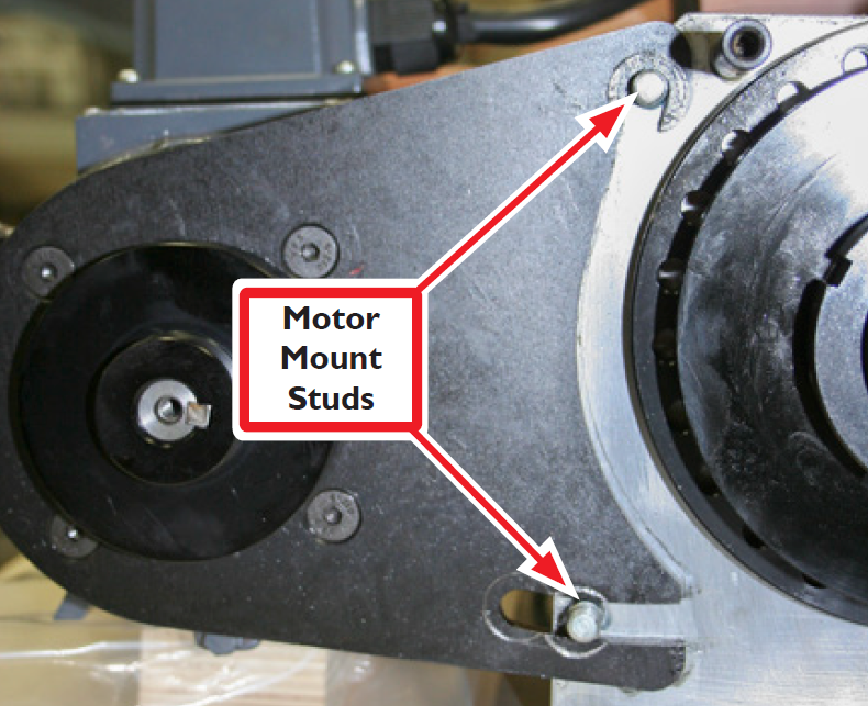
Note: Motor Bracket hooks around top Motor Mount Stud and slides on to bottom Motor Mount Stud (see Figure 8).
-
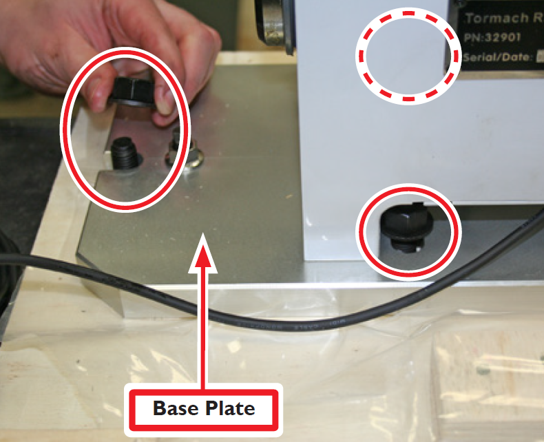
Using an adjustable wrench, loosen and remove three hex head bolts securing RapidTurn Base Plate to shipping pallet (see Figure 9); discard. Clamp hardware (see Figure 4) is used in place of hex head bolts to secure RapidTurn to machine table.
Note: One hex head bolt is on front of Base Plate; two others are underneath RapidTurn headstock (see Figure 9).
-
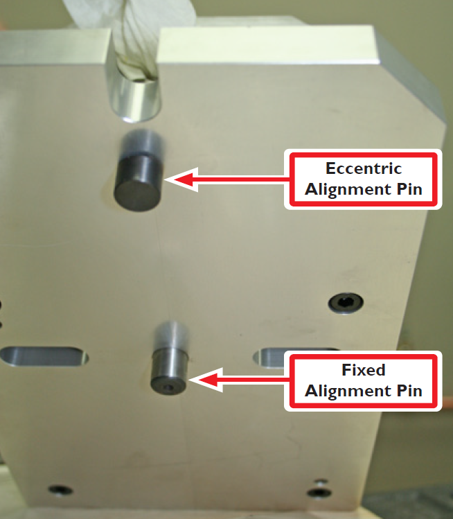
Lift up RapidTurn base plate to identify Eccentric Alignment Pin and Fixed Alignment Pin (see Figure 10). The rear (fixed) pin does not move; the forward (eccentric) pin rotates to bring RapidTurn’s headstock into alignment with mill’s X-axis. For more information, refer to ‘Align Headstock’ section.
-
Tuck Spindle Speed Sensor Cable under headstock proper to RapidTurn placement on mill.
Install Headstock
-
Using machinist's stone or similar, lightly stone surface of machine table to remove burrs.
IMPORTANT! Presence of burrs may mar or misalign the RapidTurn.
NOTE: If intending to leave RapidTurn on machine table for an extended period of time, lightly oil the machine table prior to RapidTurn placement on mill.
-
Identify Clamp Hardware set aside earlier (see Figure 4); remove flange nut from each threaded stud and set aside.
-
Jog Z-axis to move machine table as far to right of operator as possible.
-
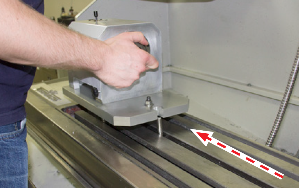
Slide one threaded stud and T-nut assembly into machine table’s center T-slot; position approximately 4” to right of Mill Spindle centerline (see Figure 11).
-
Slide two threaded stud and T-nut assemblies into T-slots as shown in Figure 11; position 6” behind front threaded stud and T-nit assembly (see Figure 11).
IMPORTANT! Ensure RapidTurn’s two alignment pins are positioned to rest in the center T-slot in line with front threaded stud (see Figure 12).
-
Carefully lift RapidTurn headstock over threaded studs and lower onto machine table (see Figure 12).
-
Thread three flange nuts set aside earlier onto exposed ends of three threaded studs on machine table until finger-tight.
Align Headstock
This procedure aligns the RapidTurn headstock with the X-axis of the mill by adjusting the Eccentric Alignment Pin.
-
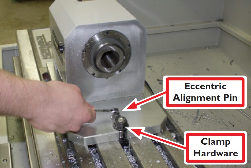
Using a 17 mm wrench, loosed the flange nut on Clamp Hardware that secures the Eccentric Alignment Pin to the base plate.
-
Using a 6 mm wrench, adjust Eccentric Alignment Pin until RapidTurn headstock is visually aligned with T-slots on machine table (see Figure 13).
-
Attach magnetic dial indicator to spindle nose; position indicator tip at edge of Headstock Face furthest away from mill column (see Figure 14).
-
Slow jog Y-axis to sweep indicator tip across Headstock face (see Figure 14)
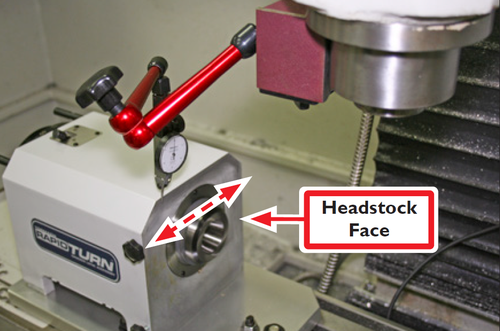
-
After reaching opposite side of Headstock face, make note of reading on dial indicator; divide that figure in half.
-
Using a 6 mm wrench, slowly adjust Eccentric Alignment Pin until reading on dial indicator reflects figure determined in step 5. Repeat steps 5-6 until reading on dial indicator does not move.
-
Using a 3/4” wrench, carefully tighten down flange nuts on Clamp Hardware. To ensure headstock has not moved during this process, slowly jog Y axis to sweep indicator tip across Headstock Face. If necessary, loosen flange nuts slightly and adjust Eccentric Alignment Pin. Repeat this step until reading on dial indicator does not move.
Reinstall Motor
-
Reattach RapidTurn motor onto two motor mount studs using an adjustable wrench, attach two M8 flange nuts set aside earlier.
NOTE: Do not completely tighten flange nuts at this time.
-
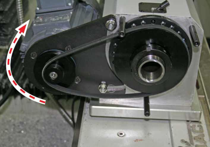
Reinstall spindle belt to bottom pair of pulleys (low speed range); tension spindle belt by lifting motor upward (see Figure 15) while tightening down two M8 flange nuts (see Figure 15 and Figure 16).
-
Using three thumbscrews set aside earlier, reinstall Belt Guard to RapidTurn.
Install and Align Tool Post
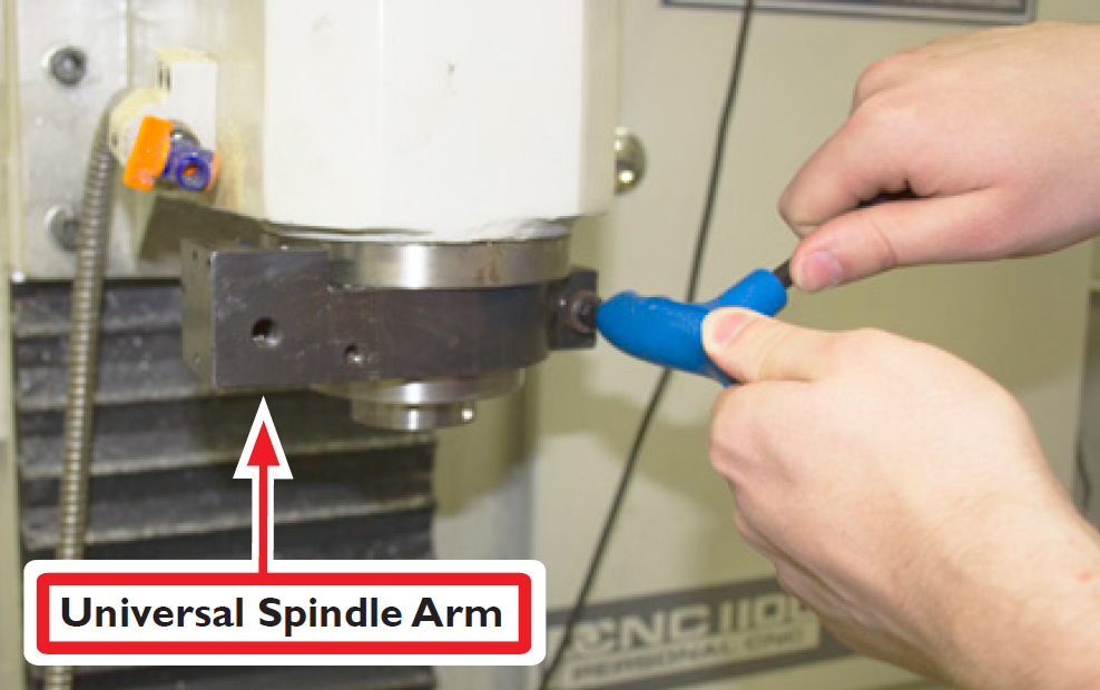
Tools for the RapidTurn are secured to the mill’s spindle nose using the Universal Spindle Arm Kit (PN 31891), which mounts a 0XA size Reverse Action Quick Change Tool Post (PN 31050). A Tool Post Stabilizer (PN 35690) is used to hold tool post steady. An optional Spindle Alignment Clamp (PN 31892) is available for use with the Universal Spindle Arm to allow quick indexing for repeatable positioning.
Important! Ensure ATC is disabled in PathPilot interface before installing tool post. For more information, refer to 'Basic Installation Procedure' section.
In order to correctly orient the tool relative to the workpiece, the tool post must be aligned so that the base of the Universal Spindle Arm is parallel to the RapidTurn’s Z-axis and the faces of the tool holders are parallel to the RapidTurn’s X-axis (see Figure 17).
-
Reset and reference mill, ensuring RapidTurn’s PathPilot interface is selected (see Figure 3).
-
After ensuring mill’s spindle nose is clean and free of debris, slide Universal Spindle Arm onto mill’s spindle nose; position with socket head cap screw to the right of operator and front face visually aligned with machine table T-slots.
-
Using an 8 mm hex wrench, loosely secure one M10 x 30 mm socket head cap screw (included) to Universal Spindle Arm (see Figure 18); do not tighten down completely.
-
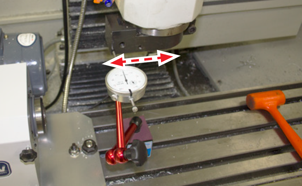
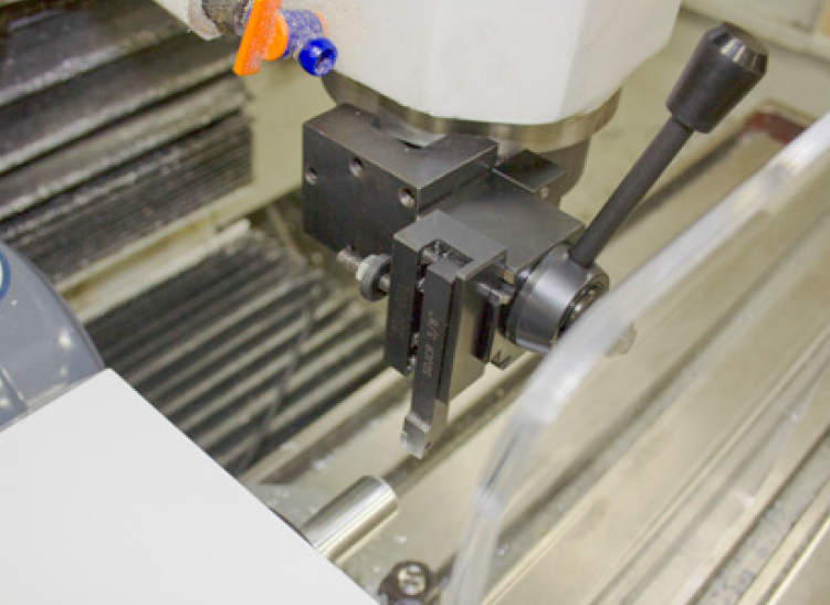
Attach magnetic dial indicator to machine table; position indicator tip so that it may be swept along front face of Universal Spindle Arm (see Figure 19).
-
Slowly jog Z-axis to sweep indicator tip back-and-forth across front face of Universal Spindle Arm. Reading on dial indicator should not move.
-
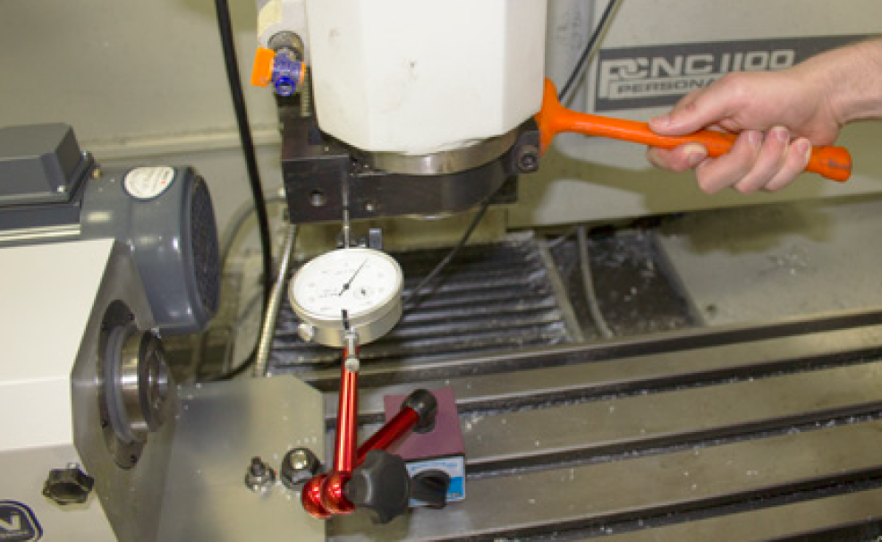
If necessary, use a dead-blow hammer to tap Universal Spindle Arm into alignment (see Figure 20). Repeat steps 5-6 until reading on dial indicator does not move.
-
Using an 8 mm hex wrench, carefully tighten down Universal Spindle Arm’s M10 x 30mm socket head cap screw.
-
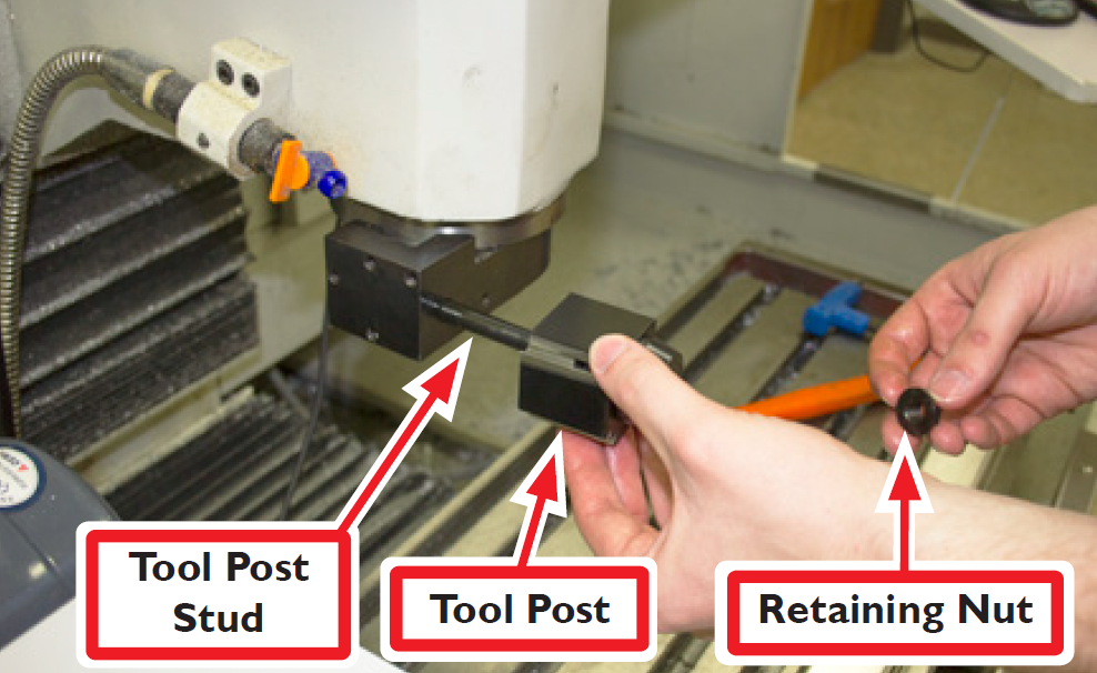
Identify Reverse Action Quick Change Tool Post (PN 31050); screw Tool Post Stud into Universal Spindle Arm and tighten (see Figure 21).
-
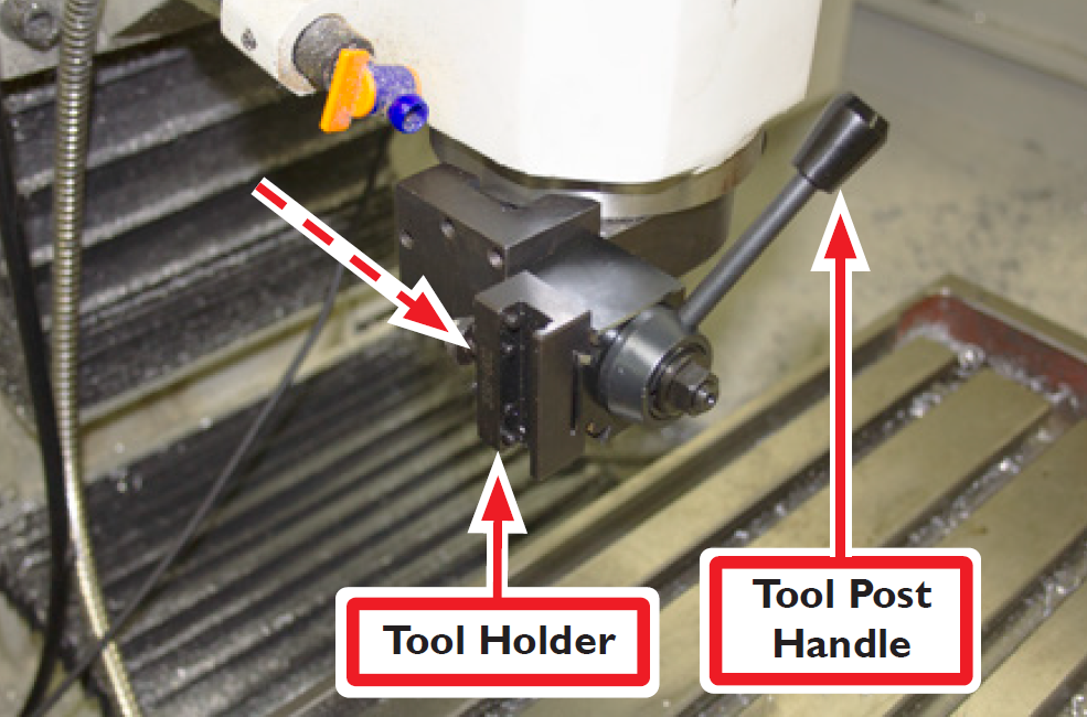
Slide Tool Post over Tool Post Stud and position so that top edge of Tool Post is visually squared up with top edge of Universal Spindle Arm; attach Retaining Nut to Tool Post Stud and tighten until finger-tight (see Figure 21).
-
Screw knob into Tool Post Handle into tool post (see Figure 22) and tighten until finger-tight.
-
Slide Tool Holder on to tool post indirection shown in Figure 22; tighten Tool Post Handle to secure tool holder in place.
-
Reset and reference mill, ensuring RapidTurn’s PathPilot interface is selected.
-
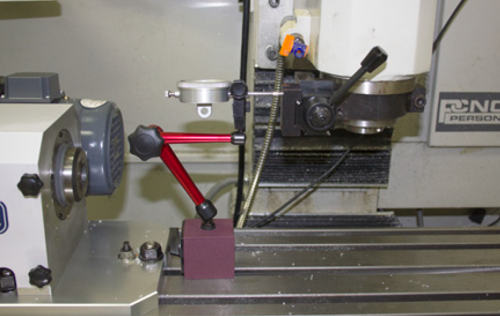
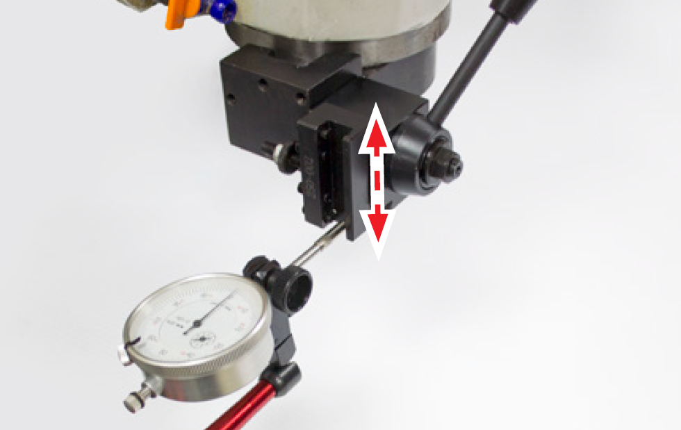
Attach magnetic dial indicator to machine table as shown in Figure 23, positioning indicator tip to be swept along vertical surface of tool holder pocket (see Figure 24).
-
Slowly jog X-axis to sweep indicator tip back-and-forth across vertical surface of tool holder pocket. Reading on dial indicator should not move.
-
If necessary, use a dead-blow hammer to tap Tool Holder into alignment. Repeat steps 14-15 until reading on dial indicator does not move.
-
Using a 14 mm wrench, carefully tighten down Retaining Nut to Tool Post Stud.
-
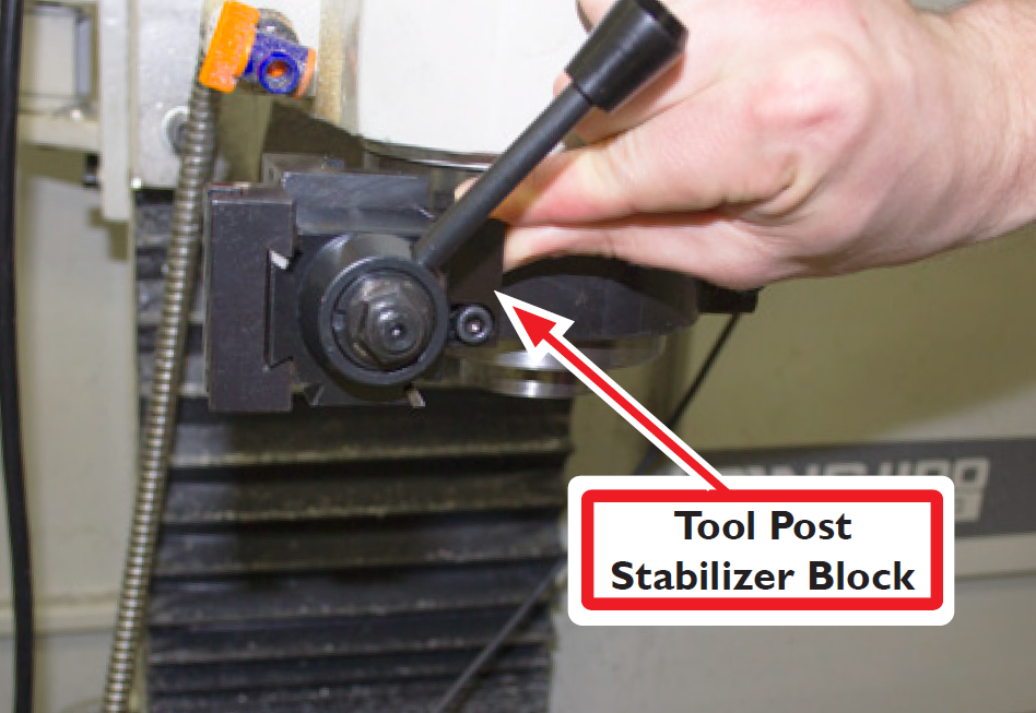
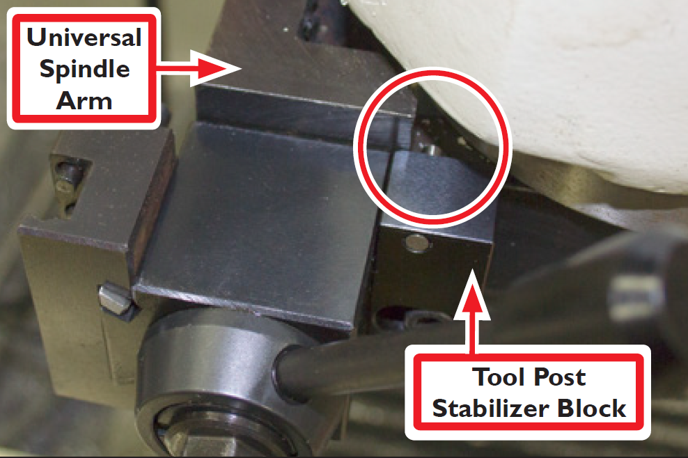
Identify Tool Post Stabilizer (PN 35690); press Tool Post Stabilizer Block flush against Tool Post on right side of operator (see Figure 25); secure with one M6 x 22 mm socket head cap screw (included).
IMPORTANT! Ensure that pin on top of Tool Post Stabilizer Block is firmly seated against upper surface of Universal Spindle Arm (see Figure 26).
Cable Connections
-
Power off mill according to the ‘Power Off/On Procedure’ detailed earlier.
-
Connect the RapidTurn as follows:
-
Plug Motor Cable (see Figure 27) into Quick Change Motor Connection Kit’s quick disconnect junction box; screw down threaded connector.
-
Plug Spindle Speed Sensor Cable (see Figure 27) into mill’s Accessory port
-
Install Chip Guard
Warning! Ejection Hazard: Tooling, fixtures, workpieces, or other loose items could become dangerous projectiles; ensure all components are appropriately secured. Do not operate with chip guard removed. Failure to do so could results in death and/or serious injury.
Before performing any tuning operations, ensure chip guard is securely installed.
-
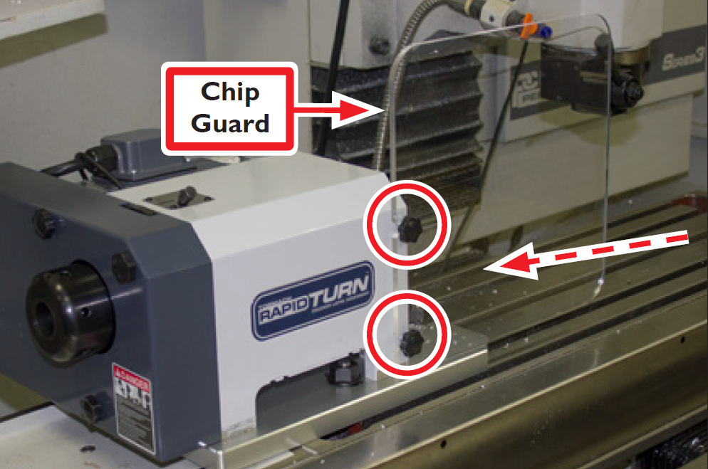
Loosen two thumbscrews on RapidTurn headstock (see Figure 28).
-
Orient Chip Guard with two slots in line with two thumbscrews on RapidTurn headstock; slide through groove on base plate as shown in Figure 28.
-
Tighten down two thumbscrews on RapidTurn headstock.
Operation
RapidTurn Axes
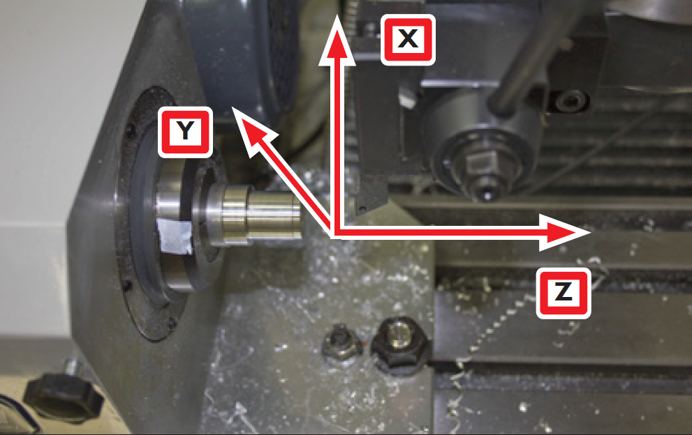
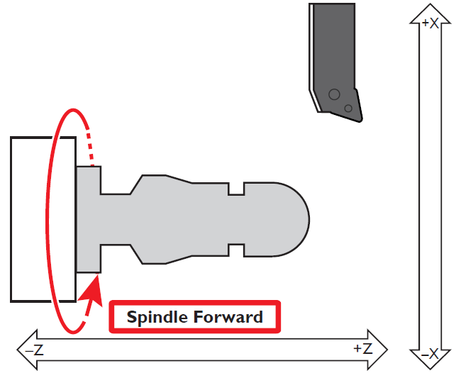
RapidTurn Axes Definition
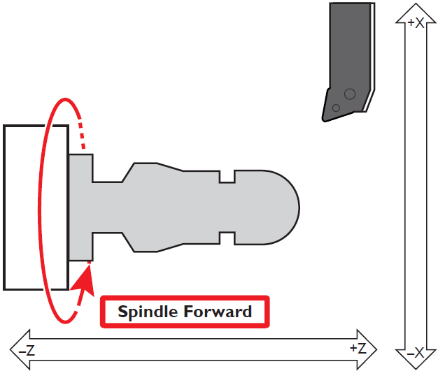
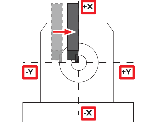
The RapidTurn has two axes of motion used for turning operations, denoted as the X-axis and the Z-axis. The Z-axis is parallel to rotational axis of the spindle along the long axis of the machine table. The X-axis is perpendicular to the Z-axis and nominally parallel to the long dimension of the mill column (see Figure 29). The -X direction is toward the machine table and +X direction is away from the machine table. The -Z direction is toward the headstock and the +Z direction is opposite the headstock.

RapidTurn Axes Control
WARNING! Motion Direction Hazard: Lathe axis orientation and motion direction differs from a PCNC mill. Do not operate RapidTurn before becoming familiar with controls. Failure to do so could result in death, serious injury, and/or machine damage.
The RapidTurn’s PathPilot interface behaves like a full-size CNC lathe. The host mill’s X-axis is reassigned as the RapidTurn’s Z-axis. Similarly, the host mill’s Z-axis is reassigned as the RapidTurn’s X-axis:
Axis Reassignment
|
Mill |
RapidTurn |
|---|---|
|
X-axis |
Z-axis |
|
Y-axis |
Y-axis (Positioning only) |
|
Z-axis |
X-axis |
The reassignment of axes can be disorienting for operators not accustomed to running CNC lathes. Use an abundance of caution and think twice about jog axis selection and anticipated motion direction when positioning the machine using RapidTurn’s PathPilot interface.
CAUTION! Collision Hazard: Any tooling, workpiece, workholding device, fixture, or accessory installed within the machine envelope presents a collision hazard during operation. Do not operate before carefully proving out part programs. Failure to do so could result in machine damage.
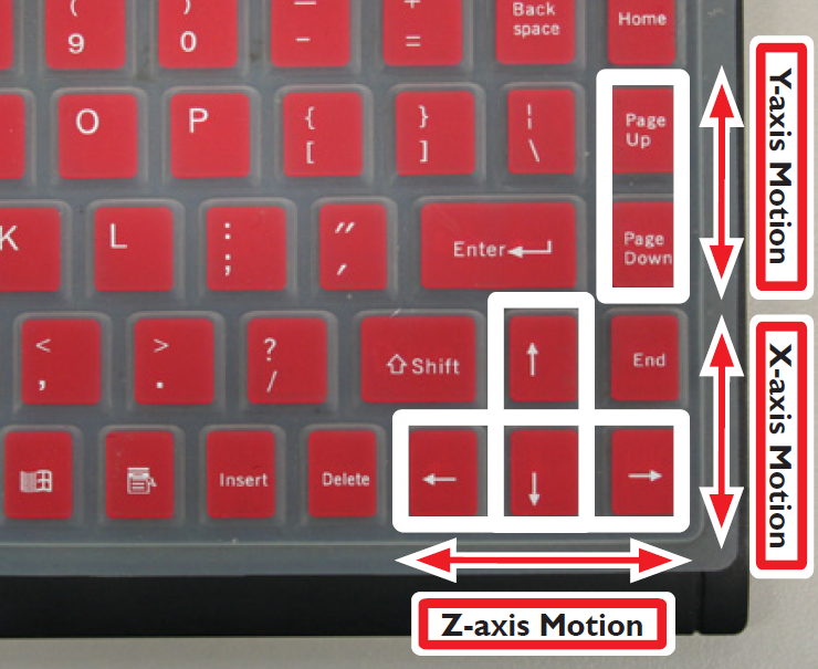
The RapidTurn can be jogged using the keyboard (see Figure 31).
IMPORTANT! Make note of keyboard function differences between the RapidTurn and the mill, as outlined in the following table. For more information on jogging the mill with the keyboard, refer to Operation, in the mill operator manual.
|
Key |
Mill |
RapidTurn |
|---|---|---|
|
Left/Right arrow |
X-axis |
Z-axis |
|
Up/Down arrow |
Y-axis |
X-axis |
|
Page Up/Page Down |
Z-axis |
Y-axis |
•Right arrow jogs Z-axis in positive Z direction (headstock moves away from mill head)
•Left arrow jogs Z-axis in negative Z direction (headstock moves toward mill head)
•Up arrow jogs X-axis in positive X direction (mill head moves up)
•Down arrow jogs X-axis in negative X direction (mill head moves down)
•Page up jogs the Y-axis in positive Y direction (table moves toward operator)
•Page down jogs the Y-axis in negative Y direction (table moves away from operator)
NOTE: Jogging is not permitted during G-code program execution or MDI moves.
Confirm Spindle Direction
Upon initial setup, confirm RapidTurn’s spindle is rotating in the correct direction.
WARNING! Ejection Hazard: Tooling, fixtures, workpieces, or other loose items could become dangerous projectiles; ensure all components are appropriately secured. Do not operate with chip guard removed. Failure to do so could result in serious injury or death.
-
Power on mill following ‘Power Off/On Procedure’, ‘Operation’; ensure Chip Guard is installed (see Figure 31).
-
To control spindle via PathPilot, flip the operator panel’s spindle mode switch to Auto (on PCNC mills, if applicable).
WARNING! Overspeed Hazard: To prevent speeds in excess of workpiece or workholding limitations, ensure spindle speed selected in PathPilot matches actual spindle belt position. Failure to do so could result in serious injury or death.
-
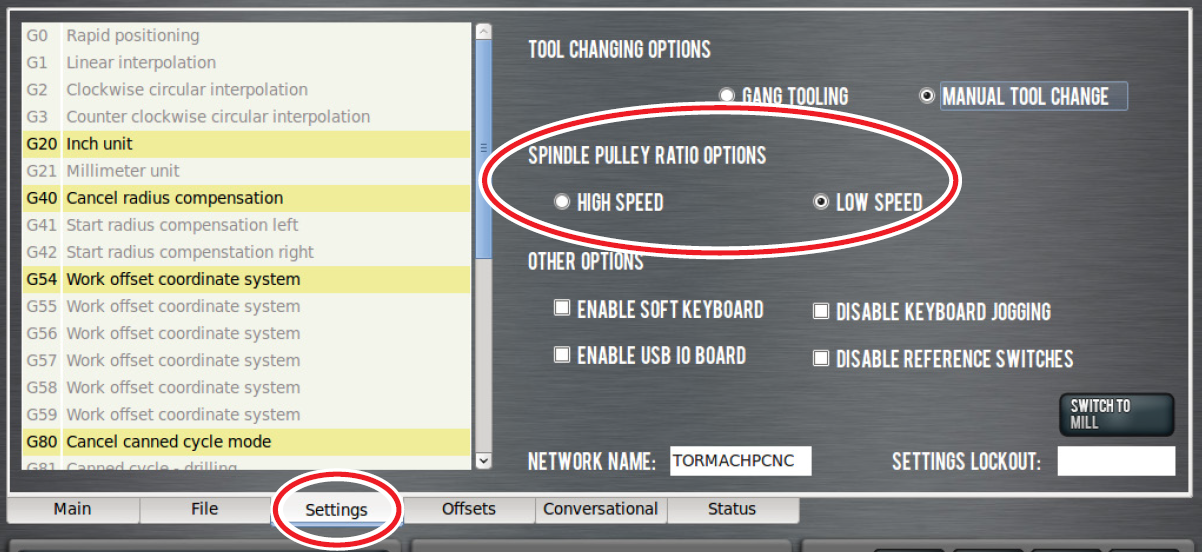
On Settings screen, select correct spindle belt position from Spindle Pulley Ratio Options: either High Speed or Low Speed (see Figure 31). For more information, refer to ‘Changing Spindle Speed Range’ section.
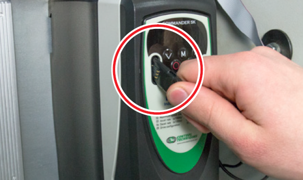
-
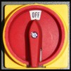
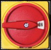
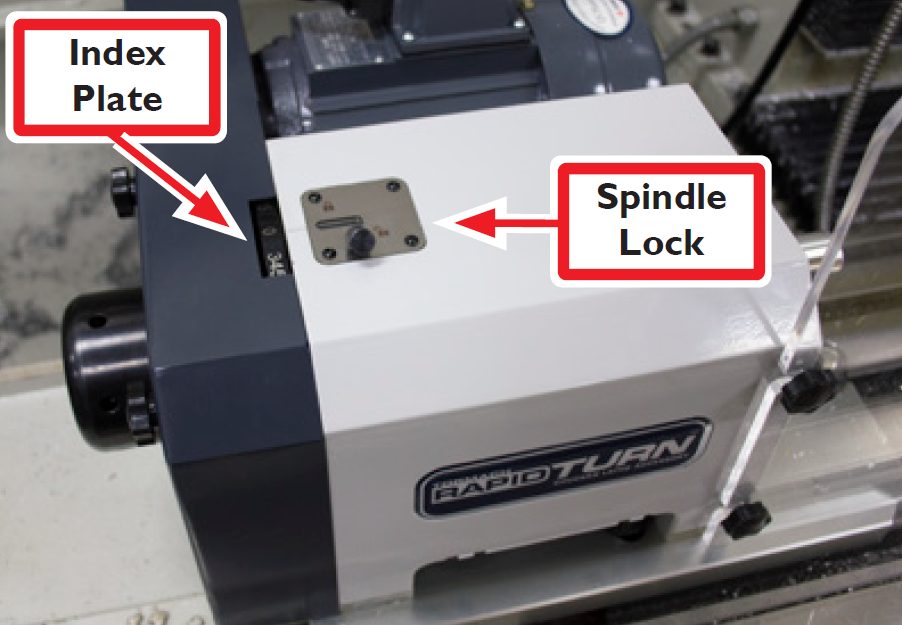
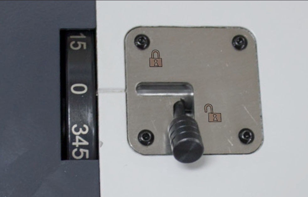
Ensure Spindle Lock (see Figure 32) is set to unlocked position as shown in Figure 33. For more information on using the spindle lock, refer to ‘Workholding’ section later in this chapter.
-
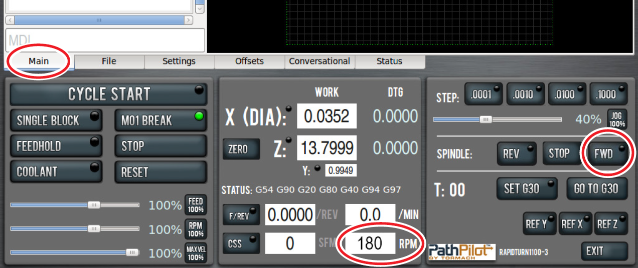
On Main screen, set chuck speed by entering 180 in RPM digital readout (DRO) as shown in Figure 34.
WARNING! Entanglement Hazard: Keep hands, hair, jewelry, and clothing away from moving parts. Failure to do so could result in serious injury or death.
-
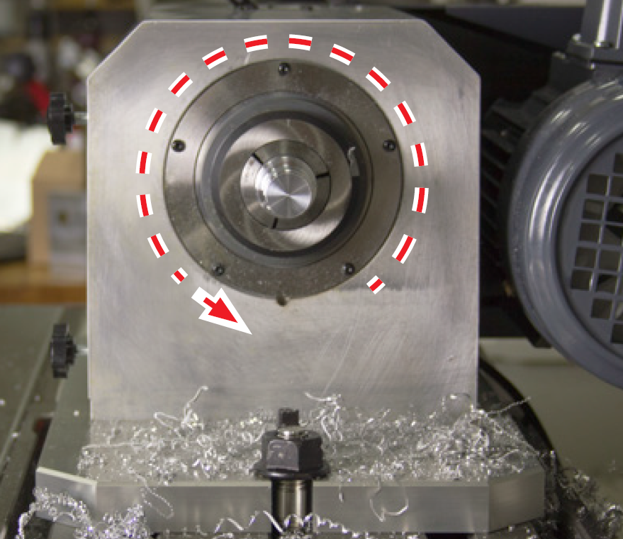
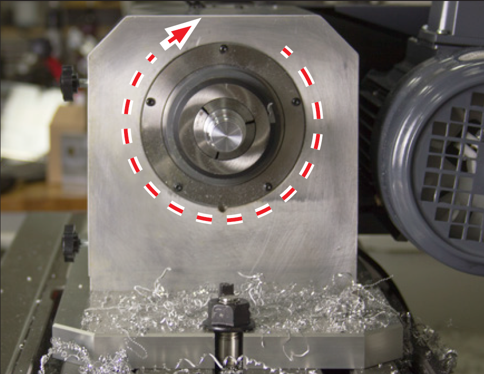
Click Spindle FWD to start spindle rotation (see Figure 35).
-
Observe spindle direction to confirm forward is correct (see Figure 35); repeat to confirm reverse is correct by clicking Spindle REV and observing spindle direction (see Figure 36). If not rotating as shown, refer to ‘Troubleshooting’, for more information.
Changing Spindle Speed Range
Spindle Speed Range
Low - 180 - 2000 RPM
High - 300 - 3500 RPM
The range change is performed by moving the spindle belt from the top pair of pulleys (high speed range) to the lower pair of pulleys (low speed range).
WARNING! Entanglement Hazard: Automatically controlled devices may start at any time. Be sure to power off machine before making any mechanical modifications. Failure to do so could result in serious injury or death.
-
Power off mill according to ‘Power Off/On Procedure’.
-
Loose and remove three thumbscrews securing belt guard; remove belt guard and set all aside.
-
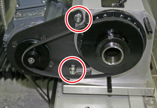
Using an adjustable wrench, loosen two M8 flange nuts securing motor bracket to RapidTurn; the belt will slacken and can be moved from one pulley to another (see Figure 37).
-
Retighten two M8 flange nuts on motor bracket; re-install belt guard.
Tooling
Tool Post Locations
Turning tools for the RapidTurn are mounted via a Reverse Action Quick Change Tool Post (PN 31050). In this configuration, most tools will be mounted with the insert facing away from the operator (see Figure 38 and Figure 39).
For information on mounting tools, refer to ‘Installation’.
Right-handed and Left-handed Tools
Tools have either a right-handed or left-handed orientation as shown in Figure 38 and Figure 39. The tool can be mounted either with the cutter facing toward the operator or turned with the cutter facing away from the operator, as shown in Figure 38 and Figure 39. Four cutting configurations are available for both a right- and left-handed tool (see Figure 38 and Figure 39). Right- and left-handed tools cut in different directions depending on the spindle rotation direction, detailed in the following table:
|
Tool |
Spindle Direction |
Cutting Direction |
|---|---|---|
|
Right-handed |
Forward Reverse |
-Z +Z |
|
Left-handed |
Forward Reverse |
+Z -Z |
Right-handed tools are commonly used for general purpose turning. Left-Handed tools are sometimes used for back chamfering or grooving.
Workholding
WARNING! Extended Workpiece Hazard: Unsupported stock can bend and whip with deadly force. Do not extend workpiece past end of spindle bore. Failure to do so could result in serious injury or death.
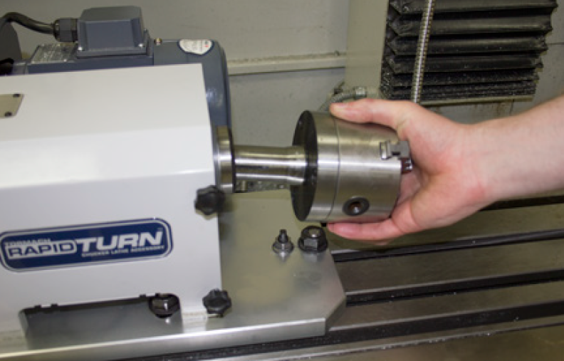
The RapidTurn’s spindle has a native 5C taper and draw tube, which allows for holding a workpiece with either a collet or 5C-compatible chuck. Less rigid workpieces, such as those with a high length to diameter ratio, may require additional support from a tailstock or other support device. For more information, refer to 'Tailstock' section.
Install RapidTurn work holder as follows:
-
Ensure contact surfaces of both the spindle’s tapered bore and the workholding device’s shank are clean and dry.
-
Insert work holder (either collet or chuck) into spindle bore as shown in Figure 40.
-
While supporting work holder, insert draw tube into opposite end of spindle bore (see Figure 40) and thread onto work holder until tight.
-
Tighten draw tube using Hand Wheel Tightening Pin (PN 37232) to avoid overtightening.
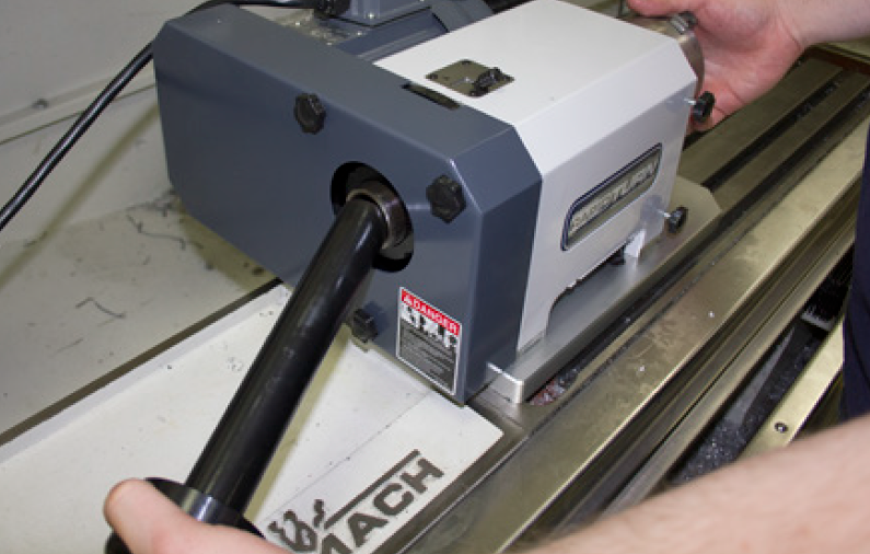
Figure 41
IMPORTANT! Do not overtighten the draw tube. To avoid overtightening, only use the Hand Wheel Tightening Pin (PN 37232) to secure the workholding device to the draw tube. Failure to do so could result in machine damage.
Collet Configuration (maximum speed rating: 3500 RPM)
For workpieces less than 1.125” in diameter, 5C collets can be used with RapidTurn’s draw tube. Tormach carries a number of 5C collets (round, square, hexagonal, serrated, and machinable).
Chuck Configuration (maximum speed rating: 2000 RPM)
For larger workpieces, Tormach carries a 3-jaw 5C Collet Chuck (PN 32855). This chuck is capable of securing workpieces by clamping on either the inner diameter or the outer diameter of the part. Because larger workpieces require lower spindle speeds and higher torque, the chuck configuration mandates the use of the low speed belt position. The low speed belt position limits the RapidTurn’s maximum speed to 2000 RPM but greatly increases the available torque.
Tailstock
The RapidTurn is compatible with Medium Tailstock for Rotary Table (PN 30272) and MT-1 Live Center (PN 34104). The tailstock supports less rigid workpieces during the machining process.
Indexing
The RapidTurn has an Index Plate (with 15 degree increments) and Spindle Lock (see Figure 32), which allows the operator to perform indexed, 4th axis operations on a mill without the need to change workholding.
Regular Maintenance
Scheduled maintenance intervals for the RapidTurn are detailed in the table below.
|
Frequency |
Item |
|---|---|
|
Daily |
Clean chips off RapidTurn, machine table, and way covers |
|
|
Spray exposed, non-painted metal surfaces areas with rust preventative |
|
|
Check spindle seal for proper seating and excessive wear |
|
Weekly |
Clean chip basket on coolant tank |
|
|
Use mild cleaner to clean all exterior surfaces (no solvents) |
Delete For information on mill-specific maintenance procedures, refer to chapter 9, Maintenance, in the mill operator manual.
Intro to PathPilot
First Part Tutorial
This chapter outlines how to make the first part with RapidTurn™ and assumes the operator has no prior experience running a part program on a CNC (computer numerically controlled) lathe, but has some degree of familiarity with a PathPilot® controlled mill. Even with previous CNC lathe experience, following this tutorial offers an introduction to the controls of the machine. After reading this chapter, read ADD LINKS FOR INTERFACE AND PROGRAMMING for details on the PathPilot operating system. This chapter is only intended to be an introduction to the PathPilot interface and several basic tasks.
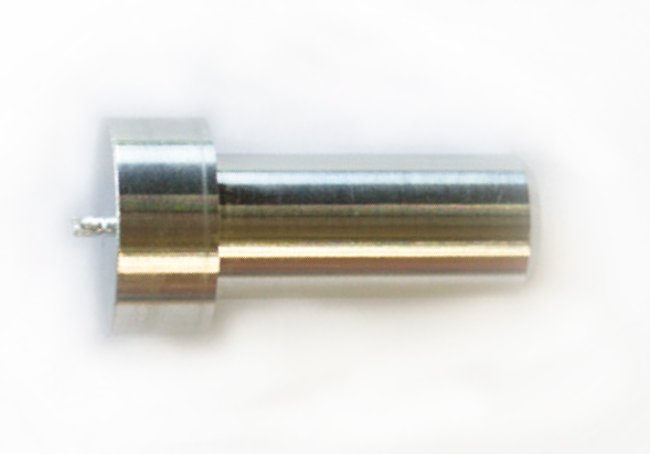
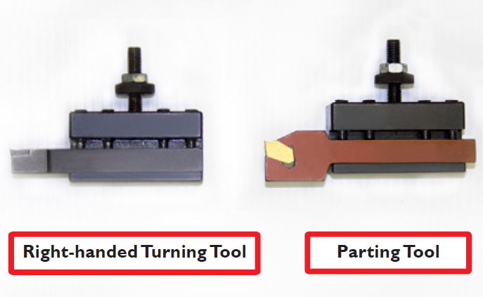
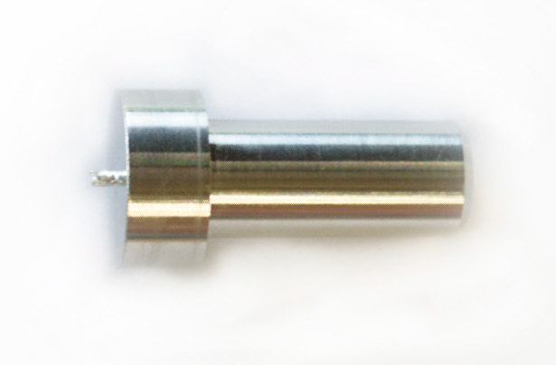
The first part program uses a right-handed turning tool and a parting tool to turn a 1” diameter aluminum workpiece down to a 0.500” diameter bushing blank with flange (see Figure 42). The following instructions will give you a quick start introduction to the lathe controls.
Reference the Machine
Follow the Power Off/On Procedure, to turn the PathPilot controller and machine on. After clicking the flashing Reset button, reference the X-, Z-, and Y-axes. The axes may be referenced in any order, but it is customary to reference the X-axis first to move the tooling as far as possible from any workpiece or chuck to avoid a crash. While the machine can be jogged before referencing, parts cannot be run until the machine has been referenced. Referencing establishes soft limits, protects from over travel, and gives meaning to work offset values. After referencing the axes, LEDs on the REF X, REF Z, and REF Y buttons illuminate. For information on manually referencing the machine, refer to the Troubleshooting section, in the mill operator manual.
Workholding Preparation
Before installing a chuck or 5C collets, ensure the contact surfaces of both the spindle’s tapered bore and the workholding device’s shank are clean and dry.
Install the workholding device by inserting it into the spindle bore and securing with the draw tube (for more information on installation of workholding, refer to Operation). Tighten the draw tube using the Hand Wheel Tightening Pin (PN 37232) to avoid overtightening.
IMPORTANT! Do not overtighten the draw tube. To avoid overtightening, only use the Hand Wheel Tightening Pin (PN 37232) to secure the workholding device to the draw tube. Failure to do so could result in machine damage.
Workpiece Preparation
Using a 1” diameter aluminum bar that is approximately 3.5” long, insert the workpiece into the chuck or 5C collet so that 2” protrudes from the jaws of the chuck or face of the collet (see Figure 43). The first 1.5” will be machined; leaving a bit more sticking out reduces risk of crashing a tool into the chuck or spindle.
Tooling Preparation
Both a right-handed turning tool and a parting tool are required for this first part tutorial (see Figure 44). Install both tools in quick change tool holders: either turning/facing or turning/boring holders.
Tool Holder Setup
-
Using Right-handed Turning Tool (see Figure 44), install tool into quick-change tool post.
-
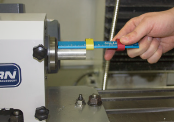
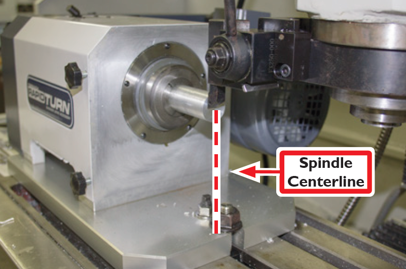
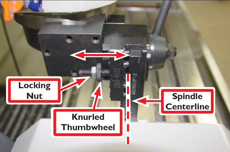
Jog machine until tool approaches workpiece; visually align tool’s cutting tip with Spindle Centerline by jogging Y-axis (see Figure 45 and Figure 46).
-
Enter 0 in Y digital read out (DRO) to zero Y-axis (see Figure 47). Press Enter after typing in the DRO to apply the value.
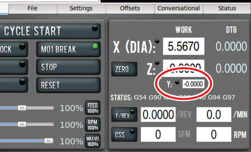
NOTE: Press Enter after any DRO changes; clicking on another DRO discards any value just entered. This is intended to avoid accidental changes.
The Y-axis is used only for initial positioning of the machine and should not need to be adjusted after this. Use the Knurled Thumbwheel on tool holder to bring the cutting tip of subsequent tools to the same Spindle Centerline (see Figure 48); adjust until the tool is in alignment, as shown in Figure 45, and secure using Locking Nut (see Figure 48).
Machine Position, Work Offsets, and Tool Offsets
Work offsets are a concept that allows the operator to think in terms of X/Z coordinates with respect to the part instead of thinking of them with respect to the machine position.
Tool offsets allow the operator to use tools of different X/Z positions. Tool offsets are broken down into two components: geometry offsets and wear offsets. Geometry offsets represent the distance from the work offset zero location to the tool’s control point. Unlike on a milling machine (where G43 must be called out to apply an offset), tool geometry offsets are automatically applied with the Txx tool change command.
Lastly, and very importantly, is the sign convention for a rear tool post CNC lathe like the RapidTurn: Z negative motion moves the tool toward the spindle, and X negative motion moves the tool toward the mill table. For more information on RapidTurn axes definitions, refer to ‘Operation’.
NOTE: All tools mounted on the mill’s spindle nose are touched off using positive X (diameter) values, and most X words in part programs for these tools will have positive values.
In many cases, PathPilot generates a warning if this rule is violated, but it has no way of preventing bad code from running.
Set the Length Units
You can program your machine in either inches or in millimeters. The machine uses the defined setting until you program a different command (G20 or G21). The settings are also retained after a power cycle, once the machine is out of reset.
Programming in Inches
Depending on your workflow, do one of the following:
-
Type G20 in the MDI line and press Enter on your keyboard
-
Program G20 in your G-code program
Programming in Millimeters
Depending on your workflow, do one of the following:
-
Type G21 in the MDI line and press Enter on your keyboard
-
Program G21 in your G-code program
Set Work Offset by Touching Off Workpiece
There are many ways of conceptualizing tool and work offsets, but we use the idea of a true positive tool length to demonstrate this first part program. When using this method, we will select a reference surface to use when establishing the work offset zero position. If you select the faces of a quick change tool holder as the reference surface, then the geometry offsets are equal in value to the stick out of the tool (i.e., a true positive tool length).
For the purposes of this tutorial, it is assumed that the quick change tool post is set up (for more information, refer to ‘Installation’) and the tool holders have been adjusted to centerline height (for more information, refer to Tool Holder Setup earlier in this chapter).
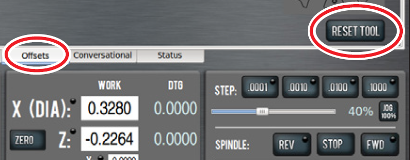
Ensure there are no tool geometry offsets currently applied in PathPilot by clicking Reset Tool on the Offsets screen (see Figure 49), which clears the geometry offsets for the currently loaded tool. If the Offsets screen displays a selection of tools (see Figure 50), this indicates no tool offsets have been applied.
Set Z Work Offset
-
Insert empty tool holder in quick change tool post.
-
Jog machine until tool hodler approaches end of aluminum bar; switch from jog mode to step mode by clicking Step .0001 button (see Figure 51).
Note: For more information on jogging controls, refer to ‘PathPilot Interface’.
-
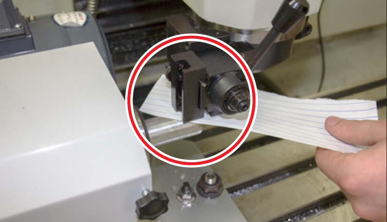
Place a piece of paper between tool holder and end of workpiece to act as a gauge; step machine toward headstock in -Z and feel for paper to bind up (see Figure 52).
-
Click the Zero button next to the Z DRO to set the current work offset Z position to zero (see Figure 51).
Set X Work Offset
-
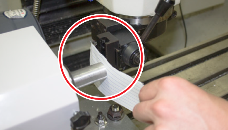
Jog machine up in X and toward headstock in Z until tool holder approaches top of workpiece; switch from jog mode to step mode by clicking Step .0001 button (see Figure 51).
-
Place a piece of paper between tool holder and top of workpiece to act as a gauge; step machine toward headstock in -Z and feel for paper to bind up (see Figure 53).
-
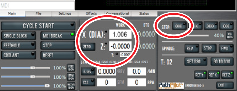
Enter diameter of the workpiece plus twice the thickness of the paper (typically 1.0 + .006) in the X (DIA) DRO to touch off at 1.006” in X (see Figure 51).
NOTE: A typical piece of paper is 0.003” thick. This value is doubled to account for the paper feeler gauge because the X (DIA) DRO always displays diameter values, not radius.
-
Jog machine back a safe distance away from workpiece.
Set Tool Geometry Offsets
Tool 1
-
Insert a right-handed turning tool into the quick change tool post.
-
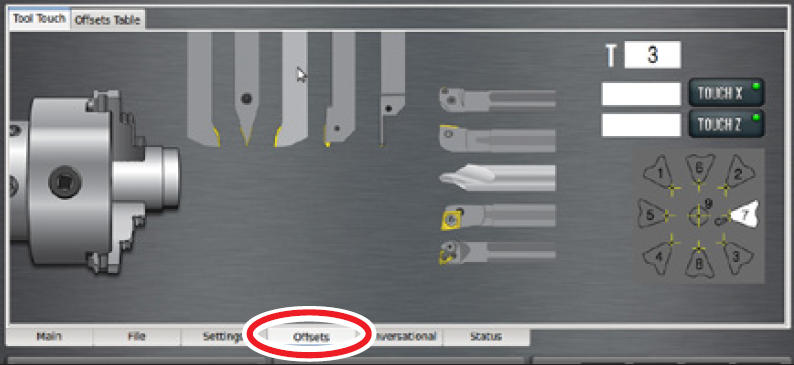
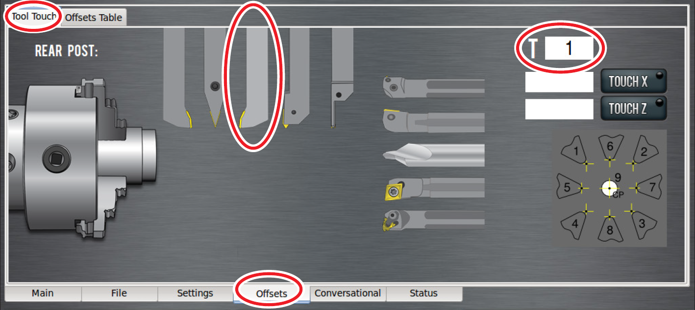
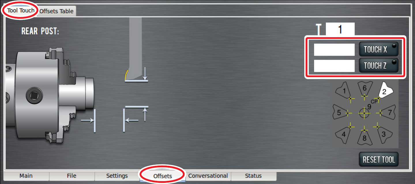
Select tool 1 in PathPilot interface – either click Tool Touch tab on the Offsets screen and type 1 in the tool T DRO (see Figure 54), or type T01 in the MDI line; click Enter.
-
On the Tool Touch tab on the Offsets screen, select right-handed turning tool (see Figure 54).
NOTE: If the wrong tool type is selected, click Reset Tool to reset the tool type (see Figure 49) and return to the tool selection screen (see Figure 54).
-
Click the Main tab (see Figure 55)
-
Jog machine until tool is near workpiece (see Figure 56).
WARNING! Ejection Hazard: Tooling, fixtures, workpieces, or other loose items could become dangerous projectiles; ensure all components are appropriately secured. Do not operate with chip guard removed. Failure to do so could result in serious injury or death.
-
Ensure chip guard is installed.
-
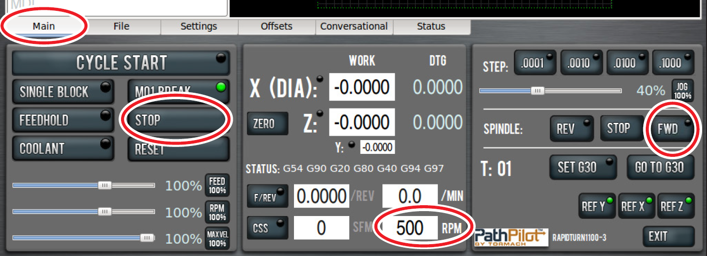
Adjust spindle speed to 500 RPMs – enter 500 in the RPM DRO and click FWD (see Figure 55), or type G97 M03 S500 in the MDI line.
-
Using the jogging controls, take a skim cut off of the diameter of workpiece. Ensure cut is long enough to measure the diameter with a micrometer.
-
Jog tool away from workpiece in Z.
IMPORTANT! Do not jog the machine in X.
-
Stop the spindle – click Stop (Figure 55), or type M05 in the MDI line.
-
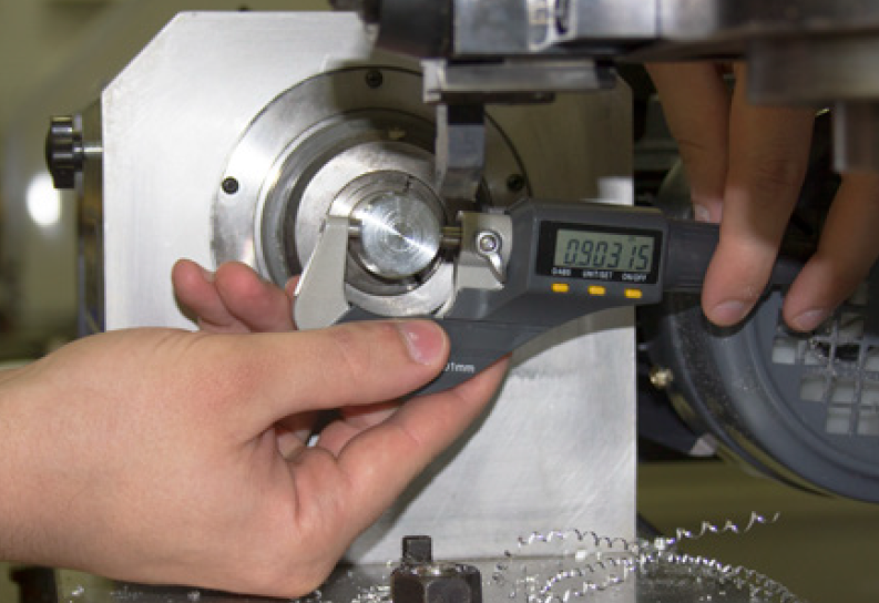
Measure diameter of skim cut on workpiece with a micrometer (see Figure 57); enter value in Touch X DRO on the Offsets screen’s Tool Touch tab and click Touch X (see Figure 58). An illuminated LED button indicates that a tool offset has been set for that tool.
-
With spindle stopped, jog machine toward face of workpiece in Z.
-
Ensure spindle speed is set to 500 RPM; click spindle FWD.
-
Jog machine toward workpiece; face the workpiece with the right-handed turning tool.
-
Stop the spindle; jog machine away from workpiece.
IMPORTANT! Do not jog machine in Z.
-
Enter 0 in Touch Z DRO; click Touch Z (see Figure 58). Use faced end of workpiece as Z-zero reference surface for all subsequent tools.
NOTE: If the tool rubs the workpiece or leaves a pip on the end of the workpiece, adjust the knurled thumbwheel and lock nut on the tool holder to better align the tool with the spindle centerline and repeat steps 12-16. For more information, ref to ‘Tool Holder Setup’ earlier in this chapter.
-
Verify that both X (DIA) DRO and Z DRO look appropriate for current position of the tool.
NOTE: The X (DIA) DRO always displays diameter values, not radius. Therefore, when the front tool post tool is 2” away from spindle centerline, the X (DIA) DRO should read 4.0”.
Tool 2
-
Jog far enough away from part to allow a tool change.
-
On Main tab, click Set G30 button to set the tool change position. And Illuminated LED indicates that a G30 position has been set.
-
On the Tool Touch tab on the Offsets screen, type 2 in the T DRO on the Tool Touch tab; click Enter.
-
Select parting tool (see Figure 59).
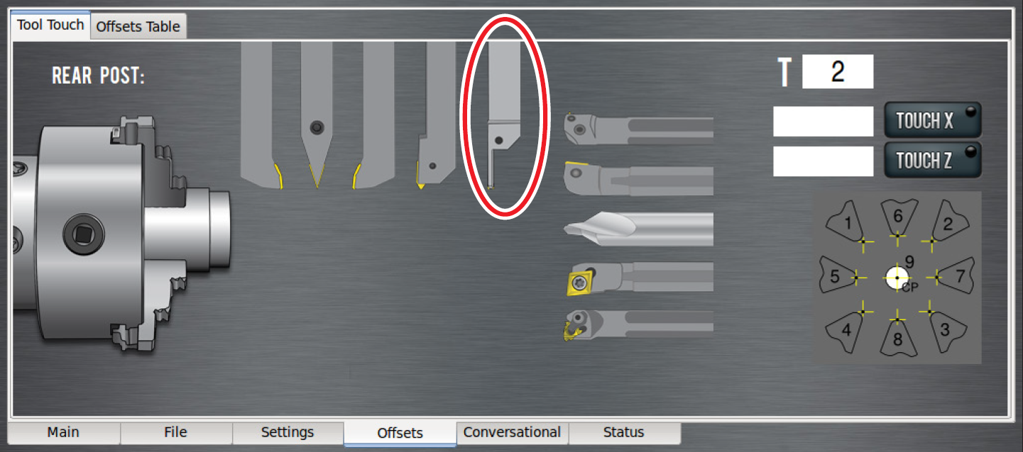
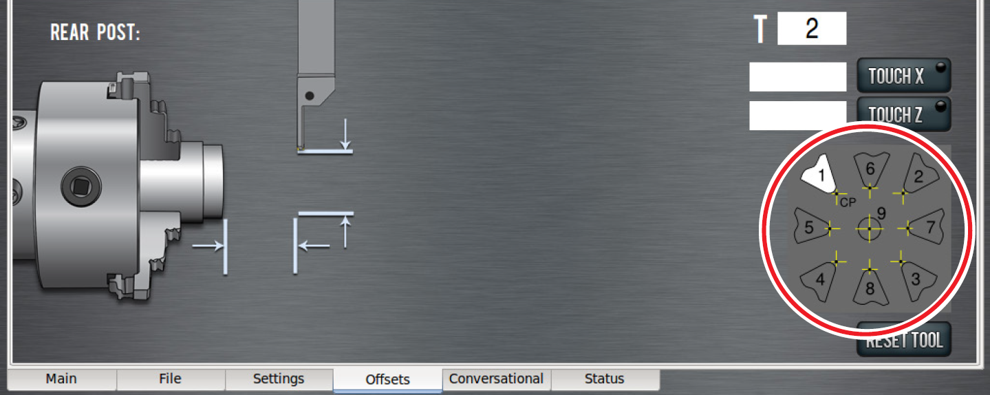
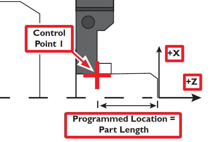
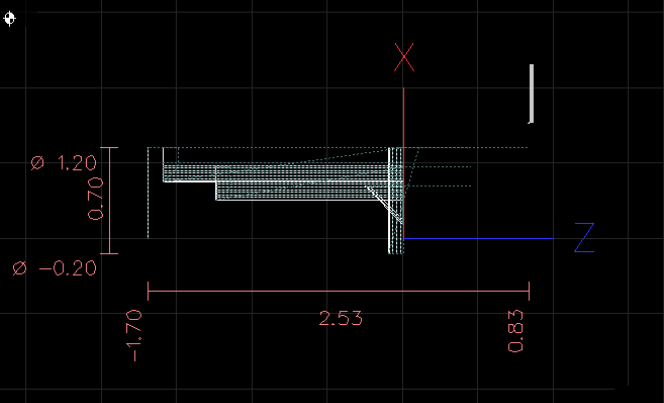
NOTE: The control point diagram (see Figure 60) illustrates the parting tool’s control point is 1 – on the right of the tool – as shown in Figure 62. This takes into account the length of the part, not the remaining stock in the spindle (see Figure 61 and Figure 62). For more information on control points, refer to ‘Programming’.
-
Start the spindle; jog machine to take a skim cut off of the diameter of the workpiece. Ensure cut is long enough to measure the diameter with a micrometer.
-
Jog tool away from workpiece in Z.
IMPORTANT! Do not jog the machine in X.
-
Stop the spindle and measure the diameter of the workpiece with a micrometer. Enter that value in the Touch X DRO; click Touch X.
-
With the spindle stopped, jog machine toward face of workpiece in Z direction.
-
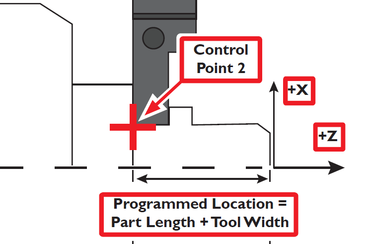
Place a piece of paper between tool and workpiece to touch off Z. Step machine to bring tool’s tip toward faced end of workpiece used to set Z-zero for tool 1. When paper binds up, stop stepping; enter thickness of paper (0.003”) plus width of parting tool insert (typically 0.120” for a GTN-3 type insert) in Touch Z DRO; click Touch Z.
NOTE: The width of the insert is included when setting tool 2 because the control point of a parting tool is the right edge, not the left edge (see Figure 61 and Figure 62).
-
Click the Offsets Table tab on the Offsets screen to double-check geometry offsets for each tool (see Figure 63). Values in the X and Z columns represent stick out of tool past faces of tool holder.
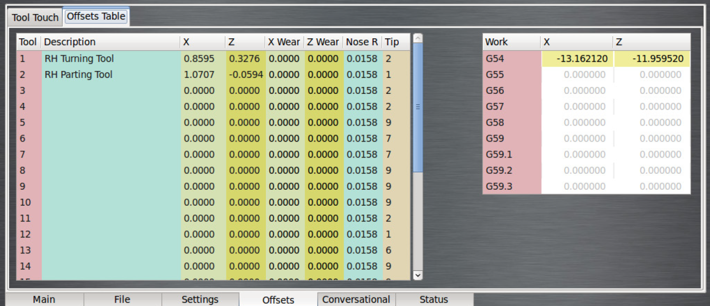
NOTE: The values in the X column are expressed in diameters, so the actual stick out is half the number shown in the column.
-
Verify tool is visually aligned with spindle centerline; adjust knurled thumbwheel and locking nut to better align tool with spindle centerline, if necessary. For more information, refer to 'Tool Holder Setup'.
Tool offsets do not need to be re-set until an insert is replaced, so long as the tools remain in their tool holders.
Write G-code
Using the conversational programming capabilities of PathPilot, the next step of this tutorial is generating G-code to produce the part. Conversational screens are divided into two sections: parameters common to most operations on the left and operation-specific parameters (including part geometry) on the right. For the purposes of this tutorial, enter in the values shown throughout this section; entry fields should be self-explanatory, but are covered in detail in following chapters.
Make note of a few things:
• The spindle speed (both roughing and finishing) is expressed in surface feet per minute (SFM), not revolutions per minute (RPM). On a CNC lathe, it is advantageous to use constant surface speed (which varies the RPM as the diameter changes) to increase part production rates, extend tool life, and maintain a better cut throughout the program.
• The feed rates (roughing and finishing) are shown in inch/rev, not in inch/min. Like constant surface speed, programming in inch/rev allows for optimal tooling performance.
The first part tutorial is broken down into five operations:
-
Face the part.
-
Turn the 1” stock down to 0.7500” along the entire length of the part (1.5”).
-
Turn the first 1.25” if part down to .5000.”
-
Chamfer the edge with a 0.050” break.
-
Part off.
Operation 1
-
Insert tool 1 into the quick change tool post.
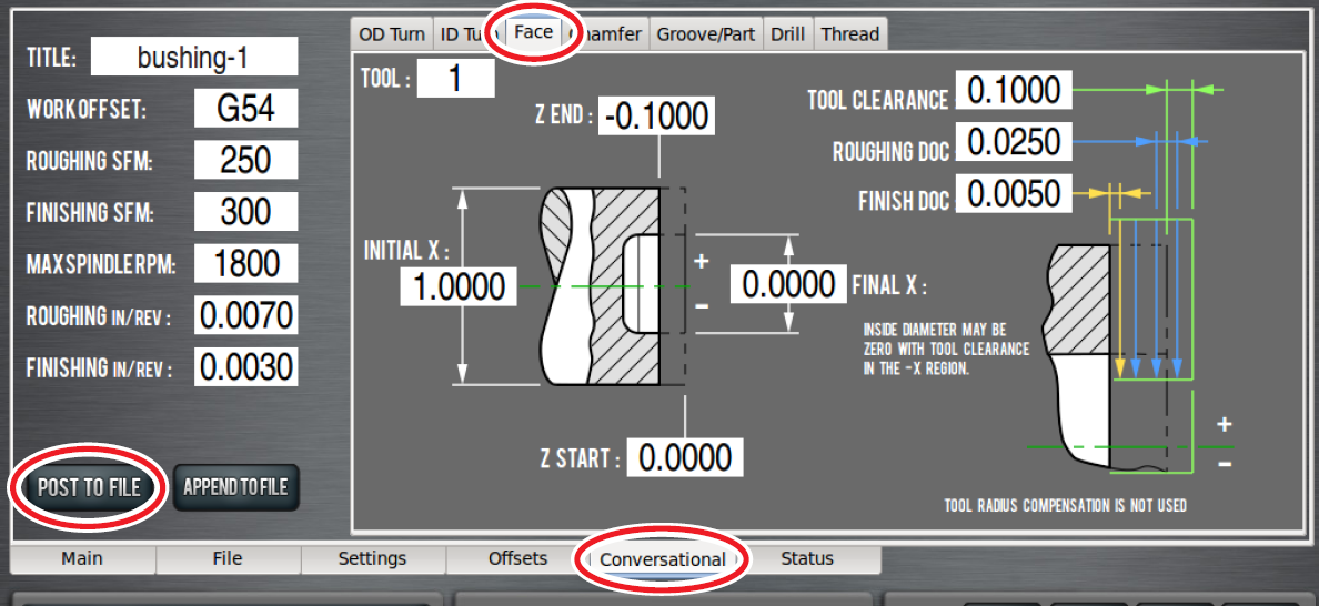
-
Click Face tab on the Conversational screen (see Figure 64) and enter values shown in Figure 64 to generate code that faces the part back to Z of -0.100”.
-
Click Post to File to save G-code (see Figure 64).
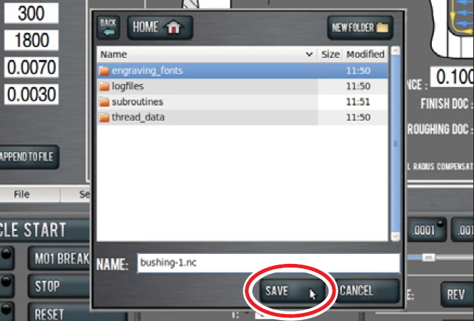
-
In dialog box, click Save (see Figure 65); file is saved and automatically loads into control, displaying tool path (see Figure 66)
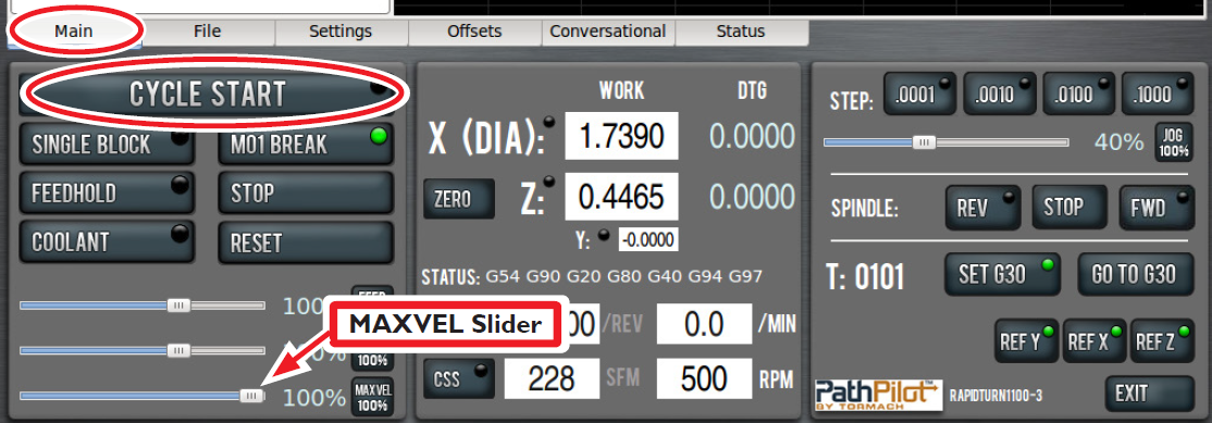
-
Click and drag MAXVEL Slider (see Figure 66) to zero percent.
-
Click Cycle Start (see Figure 66). If current tool is not tool 1 and machine is configured for manual tool changes, Cycle Start LED may flash to request tool change. Change tool in quick change tool post; click Cycle Start again to confirm.
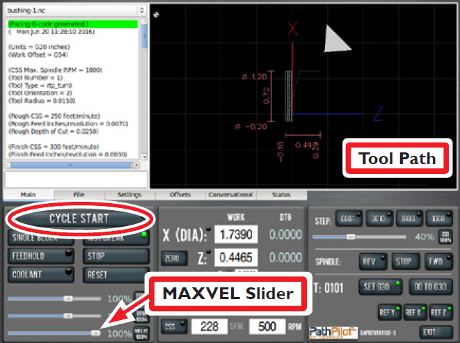
-
Click and drag MAXVEL Slider to slowly increase allowed velocity. Bring velocity back down to zero when tool is close to part; double-check DRO values. If everything looks correct, slowly move MAXVEL Slider back up to resume running part program.
Operation 2
-
Click on OD Turn tab on the Conversational screen. Enter values shown in Figure 67.
-
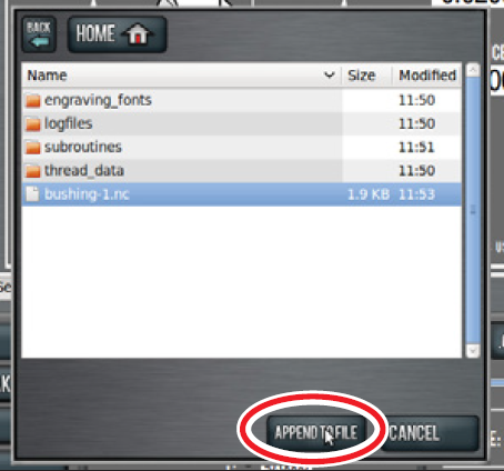
Click Append to File (see Figure 67).
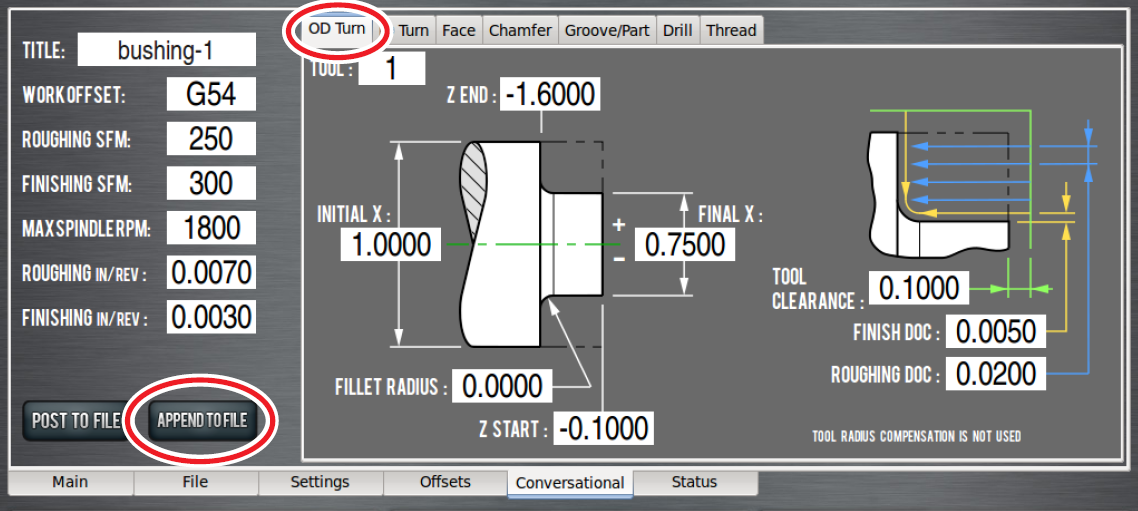
-
In dialog box, select file created in Operation 1 (see Figure 68); this adds OD turn G-code to that program.
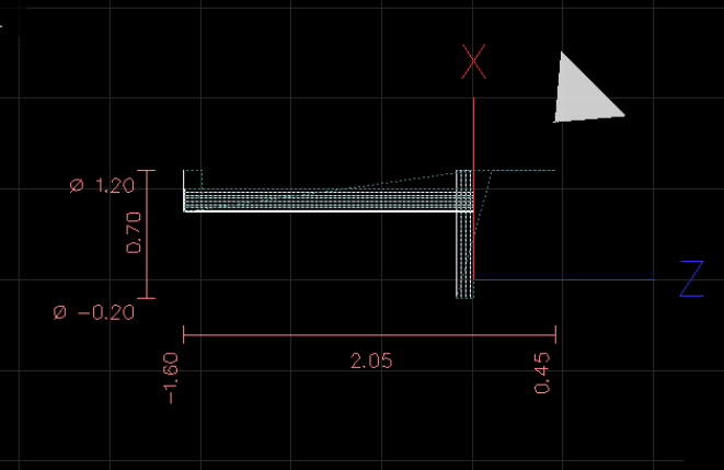
-
Confirm Append to File in dialog box (see Figure 68); this loads changes from Operation 2 to the G-code file into control and generates the tool path (see Figure 69).
IMPORTANT! Do not run this code until remainder of operations are written.
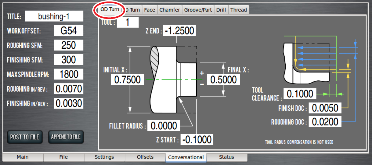
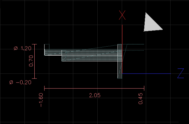
Operation 3
-
Click on OD Turn tab on the Conversational screen. Enter values shown in Figure 70 to create another OD turn routine that turns the first 1.125” of the part down to 0.5000”.
-
Click Append to File to add this code to part program and generate tool path shown in Figure 71.
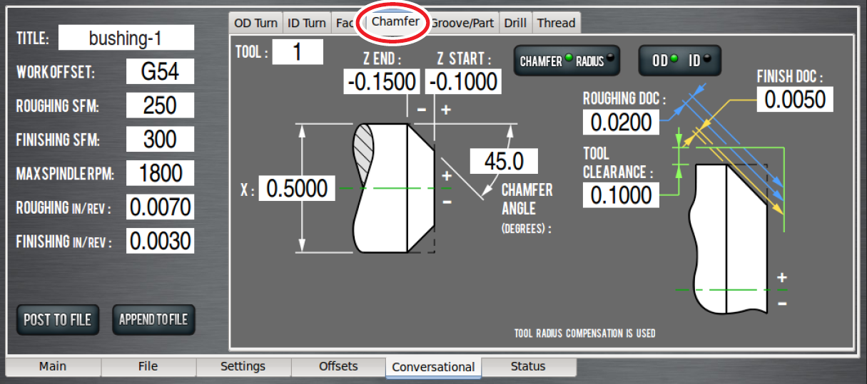
Operation 4
-
Click on Chamfer tab of the Conversational screen. Enter values shown in Figure 72 to put a small chamfer on the part.
-
Click Append to File to add this code to part program and generate tool path shown in Figure 73.
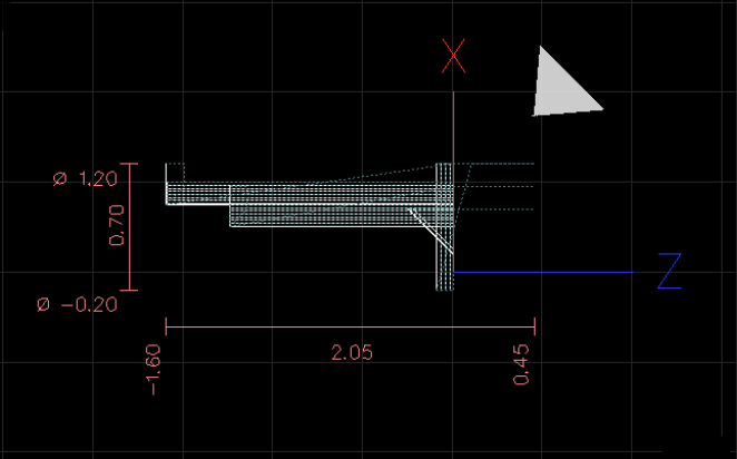
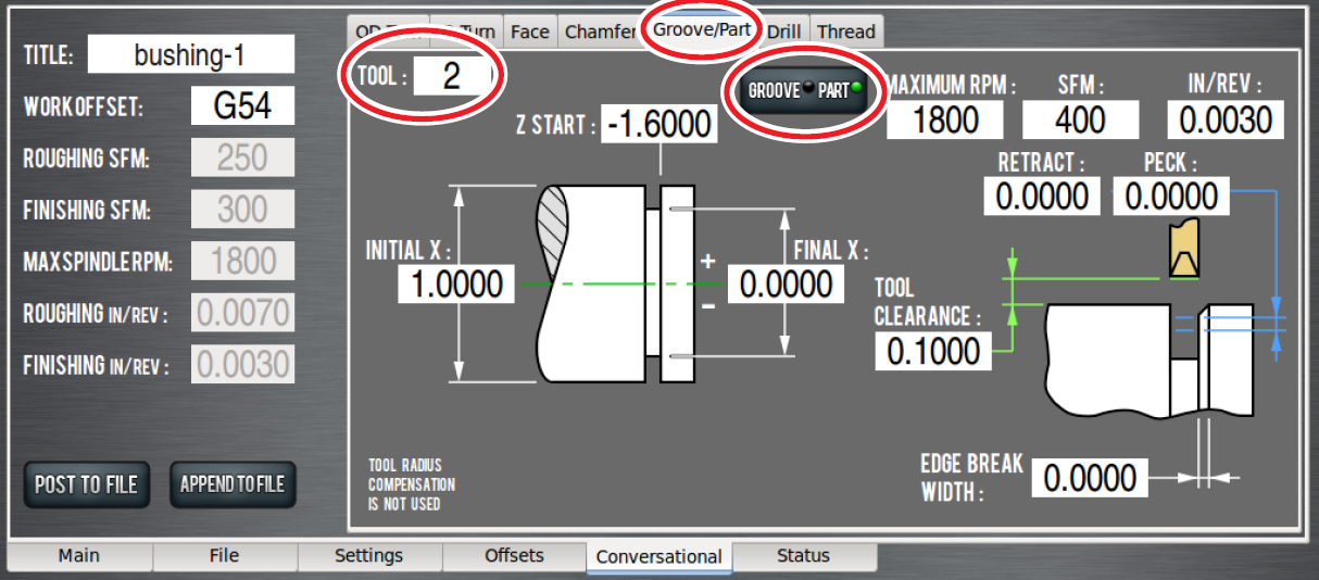
Operation 5
The final operation uses tool 2 (a parting tool) to part off workpiece.
-
Click Groove/Part tab on the Conversational screen; toggle the Groove/Part button to select the Part screen. Enter values shown in Figure 74.
NOTE: Ensure tool 2 is entered in the Tool DRO (see Figure 74). Using tool 1 generates an error message to alert that a right-hand turning tool is not a valid tool for a parting routine.
-
Click Append to File to add this code to part program and generate tool path shown in Figure 75.
Run Completed G-code Program
-
On the Main tab, click and drag MAXVEL Slider to zero percent (see Figure 76).
-
Click Cycle Start (see Figure 76); click and drag MAXVEL Slider to slowly increase allowed velocity. Bring velocity back down to zero when tool is close to part; double-check DRO values. If everything looks correct, move MAXVEL Slider back up to resume running part program.
The techniques used to program the first part (see Figure 77) form the basis of most of the operations performed on a CNC lathe.
PathPilot Interface
For an overview of the Lathe Interface of PathPilot, see PathPilot Interface Overview - 15L.
Programming
For an overview of Lathe Programming in PathPilot, see Programming - 15L.
Troubleshooting
Common issues and possible solutions specific to the RapidTurn are detailed in this chapter. For information on general techniques and mill-specific troubleshooting procedures, refer to the troubleshooting section in the mill operator manual.
RapidTurn Spindle Does Not Turn
|
Possible Cause |
Probability |
Action to Identify Cause of Problem |
Notes |
|---|---|---|---|
|
Spindle Motor not connected |
High |
Check RapidTurn motor cable is connected to Quick Change Motor Connection Kit’s junction box. |
– |
|
Spindle control switch on mill’s operator panel set to Manual. (PCNC only) |
Medium |
Check switch; set to Auto if necessary. |
– |
RapidTurn Spindle Turns in Reverse
|
Possible Cause |
Probability |
Action to Identify Cause of Problem |
Notes |
|---|---|---|---|
|
Tooling installed in reverse direction |
Medium |
Check tool’s installed direction |
Inserts face away from operator when installed on the reverse-action quick change tool post. |
|
Wiring reversed |
Low |
Check direction of RapidTurn spindle (refer to ‘Operation’, for more information). Switch to mill’s PathPilot interface and check direction of mill spindle. |
If wires were reversed when motor connection kit was installed, one or both spindles may rotate in wrong direction.
|
RapidTurn Spindle Turns at Incorrect Speed
|
Possible Cause |
Probability |
Action to Identify Cause of Problem |
Notes |
|---|---|---|---|
|
Incorrect belt position for PathPilot configuration |
High |
Check high/low spindle speed selection on Settings tab in PathPilot interface. |
– |
|
Incorrect VFD program (PCNC 1100 only) |
Medium |
Verify RapidTurn VFD programming stick is inserted into VFD’s programming slot |
– |
RapidTurn Pauses During Operation and Will Not Feed
|
Possible Cause |
Probability |
Action to Identify Cause of Problem |
Notes |
|---|---|---|---|
|
Spindle speed sensor cable not connected |
High |
Check spindle speed sensor cable is connected to mill’s Accessory port. |
Verify spindle speed sensor function by connecting sensor, completing a full rotation of RapidTurn’s spindle, and observing Encoder Z LED on Status tab in PathPilot interface. LED should illuminate once per spindle rotation. |
|
Spindle speed signal not getting to PathPilot |
Low |
Inspect connections and wiring |
Verify spindle speed sensor function by connecting sensor, completing a full rotation of RapidTurn’s spindle, and observing Encoder Z LED on Status tab in PathPilot interface. LED should illuminate once per spindle rotation. |
Diagrams and Parts Lists
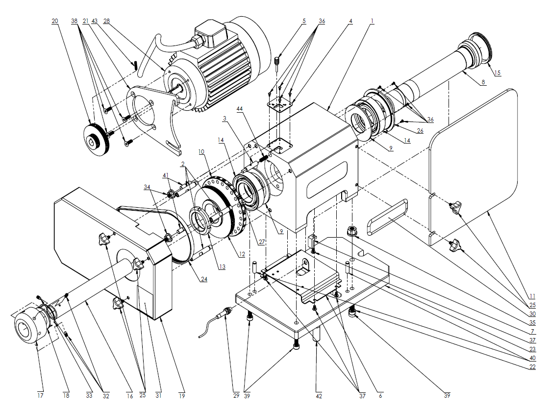
RapidTurn Assembly (Exploded View)
|
Description |
Alternative Part Number |
|
|---|---|---|
|
1 |
Headstock (PN 32902) |
– |
|
2 |
Stand Off (PN 32903) |
– |
|
3 |
Index Pin (PN 32904) |
– |
|
4 |
Spindle Lock Plate (PN 32905) |
– |
|
5 |
Spindle Lock Lever (PN 32906) |
– |
|
6 |
Sensor Bracket (PN 32908) |
– |
|
7 |
Spindle Speed Sensor Flag (PN 32909) |
– |
|
8 |
RapidTurn Spindle (PN 32910) |
– |
|
9 |
Spindle Spacer Inner (PN 32912) |
– |
|
10 |
Index Plate (PN 32913) |
– |
|
11 |
Chip Guard (PN 32914) |
– |
|
12 |
Spindle Pulley (PN 32915) |
– |
|
13 |
Bearing Nut (PN 32916) |
– |
|
14 |
Angular Contact Bearing (PN 32917) |
– |
|
15 |
V-Ring Seal (PN 32918) |
– |
|
16 |
Draw Tube Assembly (PN 37267) |
– |
|
17 |
Hand Wheel (PN 32920) |
– |
|
18 |
Thrust Bearing (PN 32922) |
– |
|
19 |
Belt Guard (PN 32923) |
– |
|
20 |
Motor Pulley (PN 32925) |
– |
|
21 |
Motor Bracket (PN 32927) |
– |
|
22 |
Eccentric Pin (PN 32928) |
– |
|
23 |
Base Plate (PN 32930) |
– |
|
24 |
Poly-Vee Belt1 (PN 32931) |
– |
|
25 |
3-wing Knob (PN 32932) |
– |
|
26 |
Front Bearing Cover (PN 33268) |
– |
|
27 |
Square Key M6 x 32 mm (PN 33304) |
– |
|
28 |
RapidTurn Spindle Motor (PN 31431) |
– |
|
29 |
Spindle Speed Sensor Assembly (PN 37261) |
– |
|
30 |
RapidTurn Decal (PN 34927) |
– |
|
31 |
RapidTurn Safety Sign (PN 35932) |
– |
|
32 |
M6 x 10 mm Dog Point Set Screw (PN 37183) |
– |
|
33 |
Retaining Ring (PN 37184) |
– |
|
34 |
Flange Nut M10 (PN 37185) |
|
|
35 |
Flange Nut M8 (PN 37186) |
|
|
36 |
M3 x 6 mm Button Head Cap Screw (PN 37187) |
|
|
37 |
M5 x 8 mm Button Head Cap Screw (PN 37188) |
|
|
38 |
M6 x 18 mm Flat Head Cap Screw (PN 37189) |
|
|
39 |
M8 x 22 mm Socket Head Cap Screw (PN 37190) |
|
|
40 |
Dowel Pin M8 x 28 mm (PN 37191) |
|
|
41 |
Threaded Stud M8 x 30 mm (PN 37192) |
|
|
42 |
Dowel Pin 5/8" x 1-1/2" (PN 37193) |
|
|
43 |
M5 x 20 mm Cup Point Set Screw (PN 37194) |
|
|
44 |
Spindle Lock Pin Compression Spring (PN 37195) |
– |
1Gates 230J Micro-V
*For part availability, please contact Tormach Technical Support
To order part numbers not listed on http://Tormach.com, email orders@tormach.com!
To view a PDF version of your manual, go to Tormach document UM10393.
If you have additional questions, we can help. Create a support ticket with Tormach Technical Support at tormach.com/how-to-submit-a-support-ticket for guidance on how to proceed.