Purpose
This document details removal and rebuilding of the PCNC 1100 stock R8 spindle.
Required Tools:
-
Pliers
-
Metric Hex Wrench Set
-
Hydraulic Press
-
Rubber Mallet
-
Phillips Screwdriver
-
Bench Vise
-
Pin Spanner Wrench
-
Latex Gloves
-
55-62 mm Hook Spanner
-
NGLI 2 Bearing Grease
-
WD-40® (optional)
-
Bearing Packer (optional)
R8 Spindle Removal
NOTE: Retain all R8 spindle assembly parts removed in this procedure for future re-install.
-
Jog spindle nose to within 6” of machine table.
-
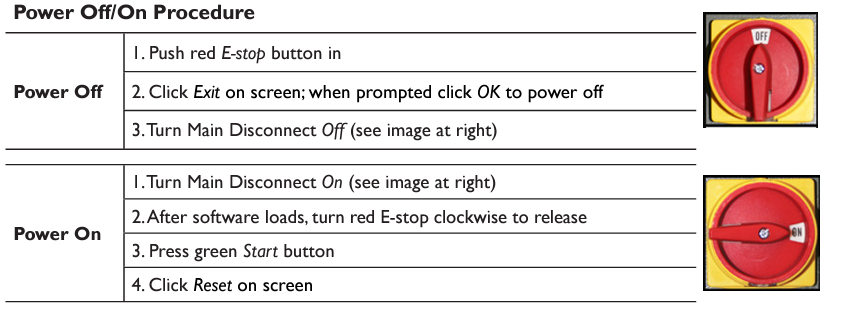
Power off mill according to Power Off/On Procedure below.
WARNING! Electrical Shock Hazard: Be sure to power off machine before making any electrical modifications. Failure to do so may result in serious injury or death.
-
Remove all tooling, fixtures, workpieces, and/or parts from mill so nothing impedes lowering of spindle later in this document.
-
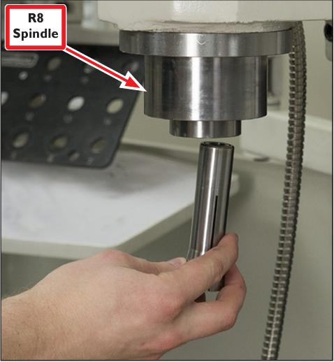
Remove Tormach Tooling System (TTS) collet or tool holder from R8 Spindle. (See Figure 1)
-
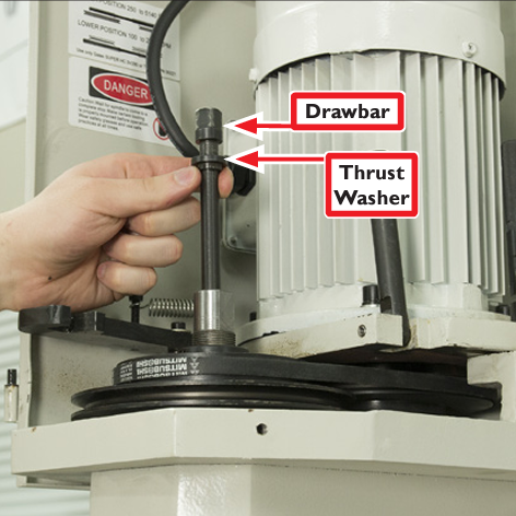
Unscrew and remove Drawbar and Thrust Washer from spindle (see Figure 2); set aside for future use.
-
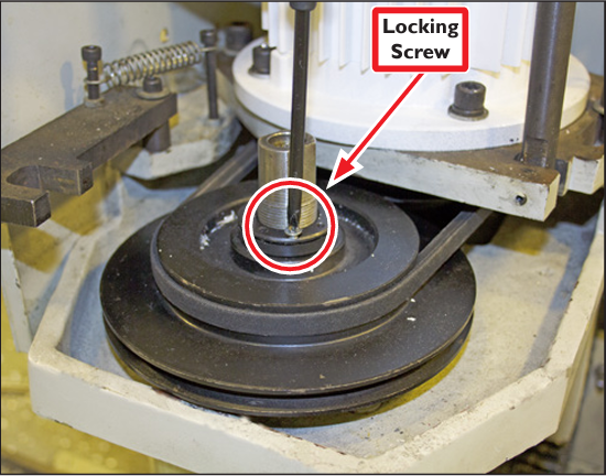
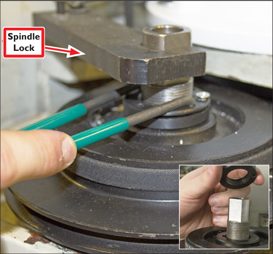
Using a Phillips screwdriver, loosen the Locking Screw on the pulley retention nut (see Figure 3).
-
With the Spindle Lock in place, use a pin spanner wrench (see Figure 4).
-
Move Spindle Lock to side; remove pulley retention nut (see Figure 4 inset); set aside for future use.
-
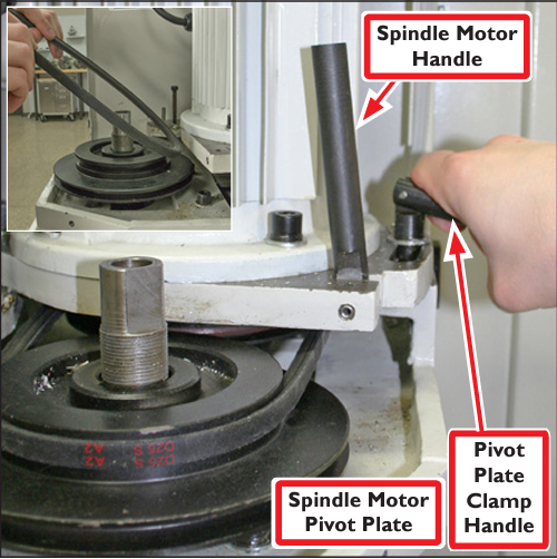
Loosen Pivot Plate Clamp Handle as shown in Figure 5. Swing Spindle Motor Handle down and move Spindle Motor Pivot Plate forward to remove spindle belt (see Figure 5 inset).
-
Swing Spindle Motor Pivot Plate back to allow spindle belt removal; set aside belt for future use.
-
Hand tighten Pivot Plate Clamp Handle.
-
Power on mill according to Power Off/On Procedure cited earlier in this document.
-
Place wood block(s) under R8 Spindle to prevent damage to both spindle and machine table; lower spindle until contact is made with block(s) as shown in Figure 6.
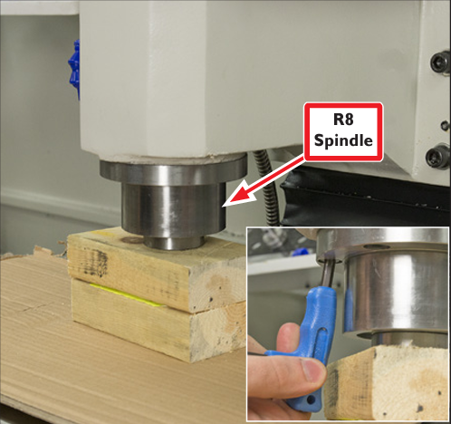
NOTE: Allow enough space between table and R8 Spindle to allow access to six socket head cap screws (see Figure 6 inset).
-
Using an M6 hex wrench, remove six socket head cap screws; set aside for future use.
-
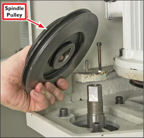
Slowly jog machine up to raise Head Casting just until Spindle Pulley can be removed (see Figure 7); set aside for future use.
NOTE: If pulley is stuck, spray with WD-40® and/or use large gear puller.
-
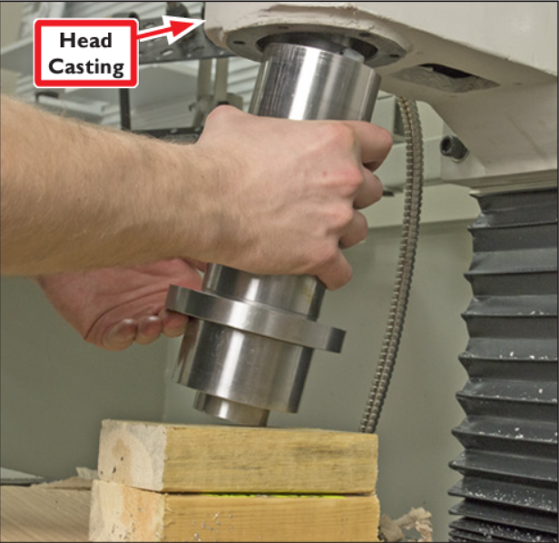
Carefully raise Head Casting slowly until R8 Spindle can be removed (see Figure 8).
R8 Spindle Rebuild
-
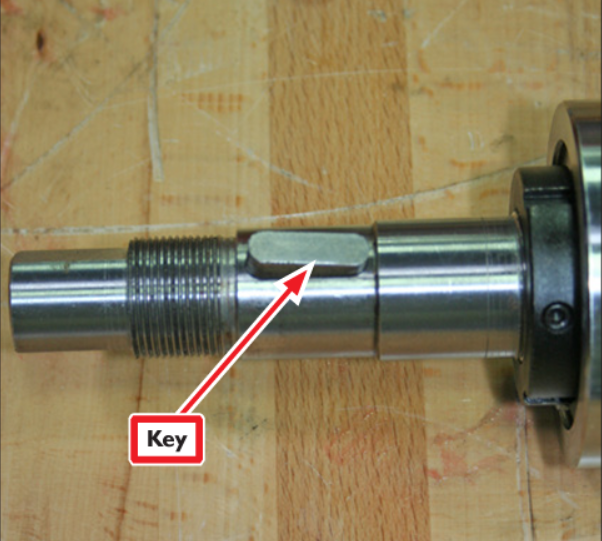
Using pliers, remove key and set aside for later use (see Figure 9).
-
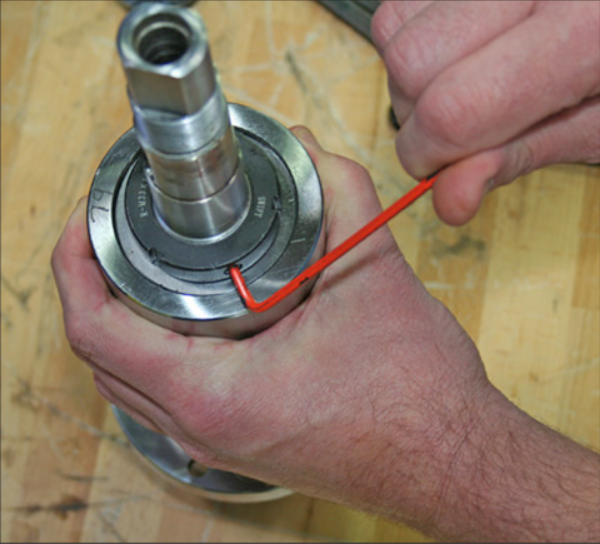
Using a 3 mm hex wrench, loosen three set screws on Bearing Preload Nut (see Figure 10).
-
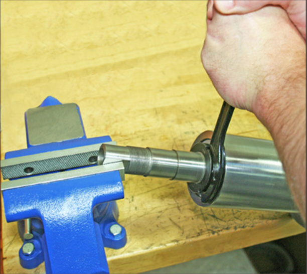
Lock spindle in vise and, using 55-62 mm Hook Spanner, loosen Bearing Preload Nut and remove (see Figure 11).
-
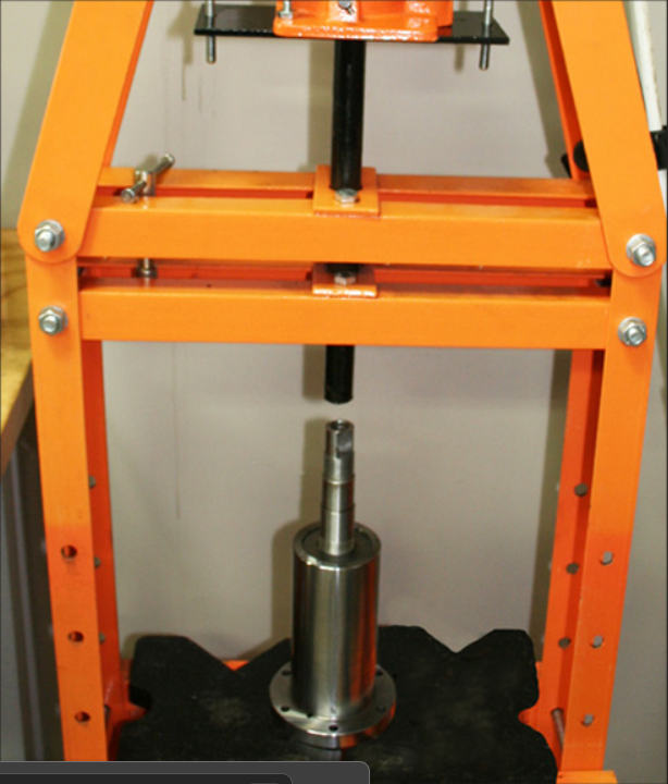
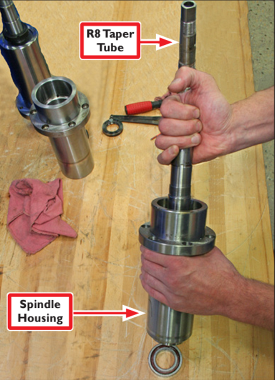
Using a hydraulic press, separate R8 Taper Tube from Spindle Housing (see Figure 12 and Figure 13); remove lower bearings.
-
Insert R8 Taper Tube into opposite end of Spindle Housing and gently tap out upper bearings (see Figure 13).
-
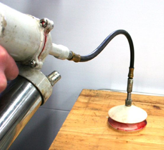
Grease new bearings (see table below), two upper and two lower by hand (Figure 14) or by using a bearing packer (Figure 15); remove excess grease.
IMPORTANT: When greasing bearings, be sure to wear protective gloves.
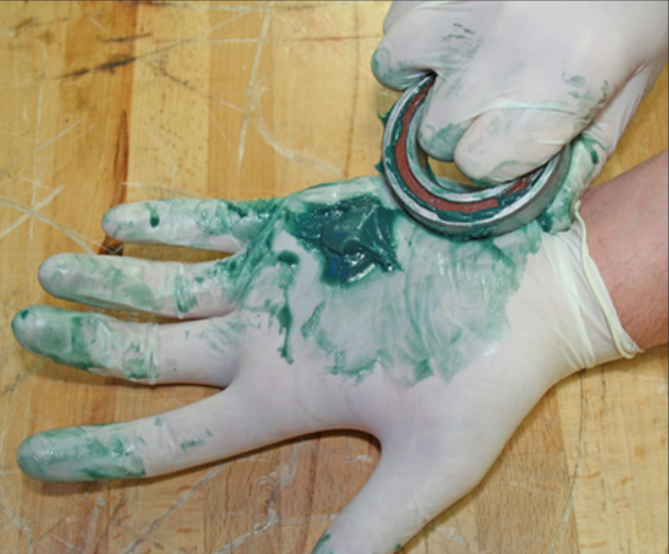
NOTE: Use general purpose NGLI 2 lithium bearing grease; 2 grams of grease for smaller upper bearings and 2.5 grams for larger lower bearings. Distribute grease uniformly into and through bearings.
|
Recommended Bearings |
PN |
|
Upper Spindle Bearings (matched pair) |
The ABEC designation for this bearing is 7007C that can be searched at other vendors. |
|
Lower Spindle Bearings (matched pair) |
The ABEC designation for this bearing is 7008C that can be searched at other vendors. |
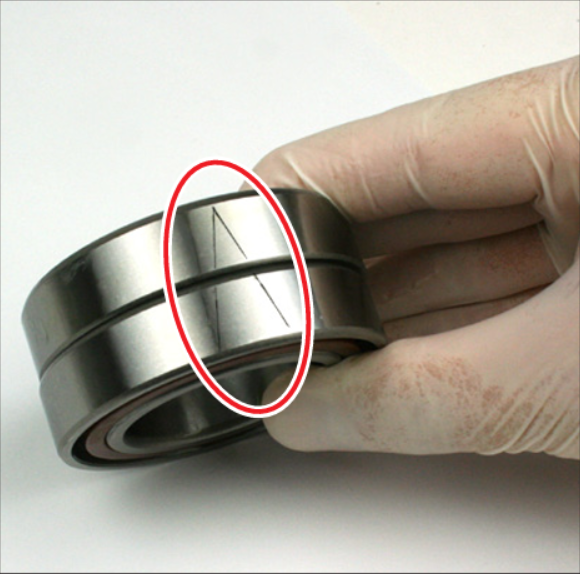
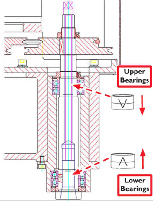
NOTE: Correct orientation of upper and lower bearings is crucial (see Figure 16 and Figure 17).
-
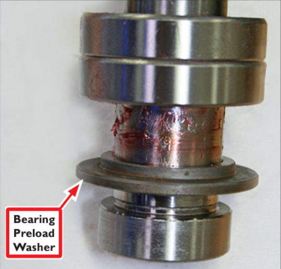
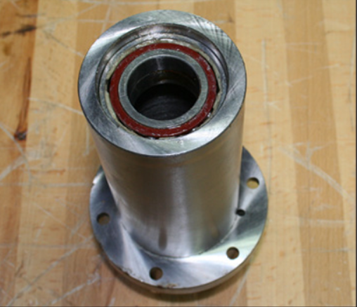
Slip Bearing Preload Washer onto R8 Taper Tube (see Figure 18) and slip on two Lower Bearings. Install two Upper Bearings into top of Spindle Housing (see Figure 19).
-
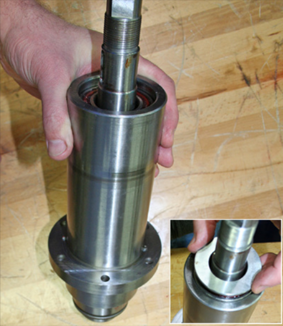
Insert R8 Taper Tube through both Spindle Housing and Upper Bearings (see Figure 20).
-
Slip Bearing Preload Washer onto R8 Taper Tube.
-
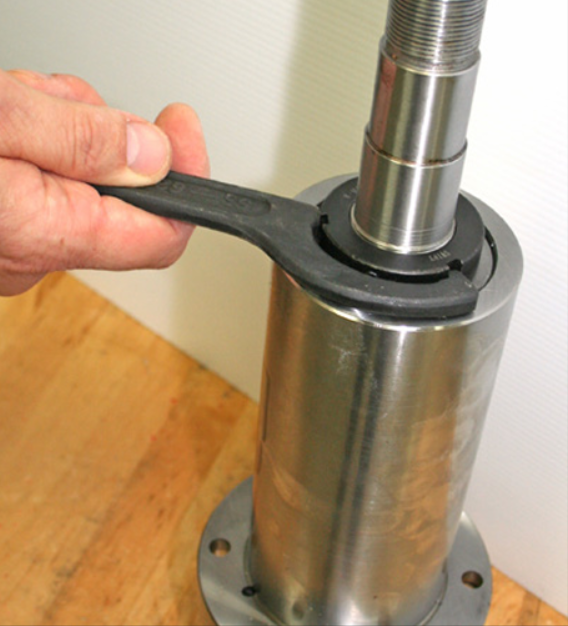
Screw on Bearing Preload Nut and, using a 55-62 mm Hook Spanner, tighten to seat bearings (see Figure 21).
-
Once seated, set bearing preload by loosening Bearing Preload Nut slightly, and then re-tighten until solid contact is made; tighten approximately 5° further.
-
Tighten three set screws on Bearing Preload Nut (see Figure 10).
-
Re-insert Key (see Figure 9) and tap in place with rubber mallet.
NOTE: If preload is too tight excessive wear and temperatures above 155° F (70° C) may result. If temperatures at spindle measure above 155° F (70° C), reduce preload.
-
To re-install rebuilt spindle, reverse all instructions detailed in R8 Spindle Removal section.
To view a PDF version of this Service Bulletin, go to Service Bulletin SB0047.
If you have additional questions, we can help. Create a support ticket with Tormach Technical Support at tormach.com/how-to-submit-a-support-ticket for guidance on how to proceed.