Purpose
This document gives instructions on installing and using the microARC 4.
Product Information
Product: microARC 4 - 100 mm 4th Axis (PN 38412)
Install the A-Axis Driver
The installation of the A-axis driver varies depending on which machine you have. Do one of the following:
Install the PCNC 440 Driver and Wiring Kit (PN 38712)
Install the M/MX A-Axis Driver (PN 38954)
Install the PCNC 440 Driver and Wiring Kit (PN 38712)
Complete the following steps in the order listed:
IMPORTANT! Even if you've already installed a 4th axis driver in your machine, you must set the DIP switches as detailed below
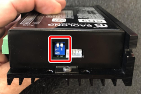
Set Driver DIP Switches
Set the DIP switches on the motor driver as detailed in the following table.
|
PCNC440 - microARC 4 |
|
|
Dip Switch |
Position |
|
1 |
Off |
|
2 |
Off |
|
3 |
On |
|
4 |
On |
|
5 |
On |
|
6 |
On |
|
7 |
On |
|
8 |
Off |
|
9 (Top) |
Off |
|
10 (Top) |
Off |
Install the A-Axis Motor Driver
WARNING! Electrical Shock Hazard: You must power off the machine before making any electrical connections. If you don't, there's a risk of electrocution or shock.
-
Power off the machine and the PathPilot controller.
-
Push in the machine's red Emergency Stop button, which removes power to motion control.
-
From the PathPilot interface, select Exit.
-
Turn the Main Disconnect switch to OFF on the side of the electrical cabinet.
-
-
Verify that you've correctly set the DIP switches on your stepper driver as detailed in "Set Driver DIP Switches".
-
Remove the electronics enclosure panel and the Z column cover on the rear of your machine.
-
Thread the two spade terminals on wires 200 and 201 through the Z column and connect them to V- (200) and V+ (201).
NOTE: If you already have a SmartCool™ or an ATC installed, the 4th axis shares those terminals.
-
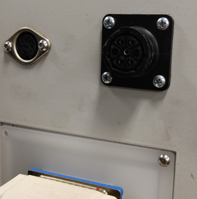
Remove the square knockout panel on the side of the cabinet and install the circular connector.
You will need to disconnect wires 320 through 323 from the green terminal block to feed them in from the outside.
-
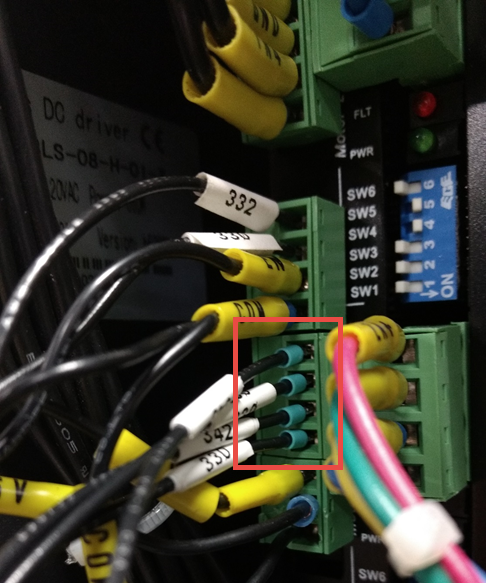
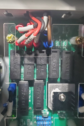
Reconnect the four wires (320 - 323) that you fed through the knockout to the 4th axis terminal block in the order shown in the following image.
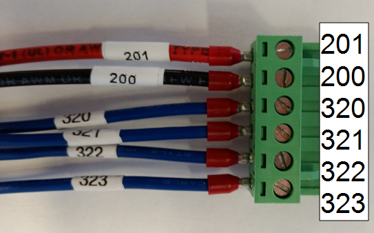
-
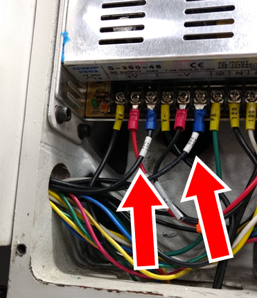
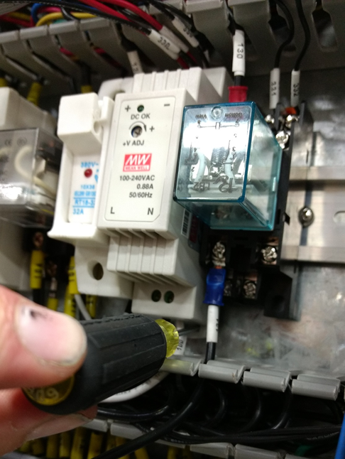
Using a flat blade screwdriver, unclip the 24V power supply from the DIN rail and tilt it out of the cabinet.
-
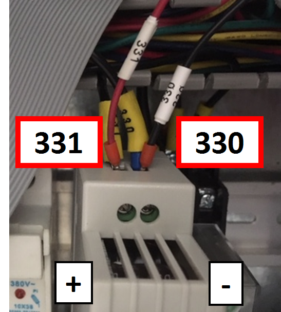
Connect the wire labeled 331 alongside the existing wire on the + output side of the 24V power supply.
-
Connect the wire labeled 330 alongside the existing wire labeled 330 on the - output side of the power supply.
-
Gently tug on each of the power supply wires to verify that they're firmly seated in the terminals. Then, clip the power supply back to the DIN rail.
-
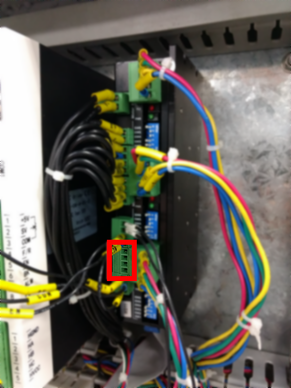
Remove the empty green connector from OUT3 and OUT4 on the machine control board. You'll replace it with the one supplied on your 4th axis wiring harness.
-
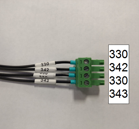
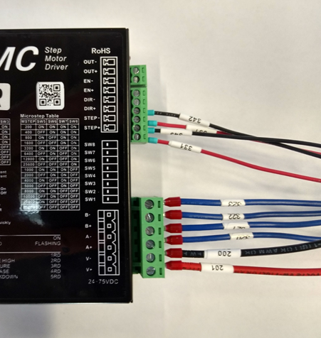
Wires 343, 330, 342, and 330 are already preinstalled in a replacement connector, corresponding to positions 3+, 3-, 4+, and 4- on the machine control board.
-
Install the connector on the machine control board.
-
Plug the remaining two 6-pin connectors into the 4th axis stepper driver.
-
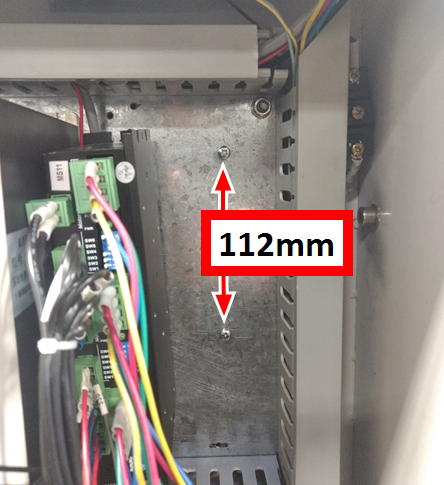
Drill and tap two M4 holes with a 112 mm spacing on the back panel of the electrical cabinet to mount the stepper driver.
-
Tuck all wires into wire troughs and reinstall the rear panels on the machine.
Configure PathPilot
You must verify that the PathPilot controller is updated to the latest version of PathPilot. This is because only PathPilot v2.7.2 and later has settings required to use a microARC 4 configuration. For information, see the PathPilot support center.
To configure PathPilot:
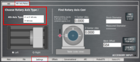
From the Settings tab, select the 4th Axis Rotary tab. Then, from the 4th Axis Type drop-down menu, select 4" 4th Axis.
NOTE: Once you change the axis scale, you may see a message indicating a Joint 3 following error. If you do, select Reset, and the new axis will function as normal.
Install the M/MX A-Axis Driver (PN 38954)
Complete the following steps in the order listed:
IMPORTANT! Even if you've already installed a 4th axis driver in your machine, you must set the DIP switches as detailed in "Set the Driver DIP Switches" below.
Set the Driver DIP Switches
Set the DIP switches on the motor driver as detailed in the following table.
|
M/MX - microARC 4 |
|
|
Dip Switch |
Position |
|
1 |
On |
|
2 |
On |
|
3 |
Off |
|
4 |
On |
|
5 |
On |
|
6 |
On |
|
7 |
On |
|
8 |
Off |
Install the A-Axis Motor Driver
WARNING! Electrical Shock Hazard: You must power off the machine before making any electrical connections. If you don't, there's a risk of electrocution or shock.
-
Power off the machine and the PathPilot controller.
-
Push in the machine's red Emergency Stop button, which removes power to motion control.
-
From the PathPilot interface, select Exit.
-
Turn the Main Disconnect switch to OFF on the side of the electrical cabinet.
-
-
Verify that you've correctly set the DIP switches on your stepper driver.
-
Remove the top, right, and middle (above the DC-BUS board) wire trough covers in the electrical cabinet.
-
Find the ribbon cable (labeled 423.4) in the top wire trough.
-
Find the green connector and wires in the right wire trough.
-
Install the motor driver in the electrical cabinet with a #2 Phillips screwdriver.
-
Connect the ribbon cable to the motor driver.
-
Apply dielectric grease to the power connector, and then connect it to the motor driver.
-
From the green connector, follow wire 240 (blue) and wire 241 (brown) to where they end in the wire trough and pull them out.
-
Connect the loose end of wire 241 (brown) to the A+ terminal on the DC bus board and connect wire 240 (blue) to the A- terminal of the DC bus board.
-
Put back the wire trough covers.
Configure PathPilot
You must verify that the PathPilot controller is updated to the latest version of PathPilot. This is because only PathPilot v2.7.2 and later has settings required to use a microARC 4 configuration. For information, see the PathPilot support center.
To configure PathPilot:
-
From the Settings tab, select the 4th Axis Rotary tab. Then, from the 4th Axis Type drop-down menu, select 4" 4th Axis.

NOTE: Once you change the axis scale, you may see a message indicating a Joint 3 following error. If you do, select Reset, and the new axis will function as normal.
Set Up the microARC 4
Complete the following steps in the order listed:
Required Tools
This procedure requires the following tools. Collect them before you begin.
-
3 mm hex wrench
-
Dead-blow hammer (or similar)
-
Magnetic dial indicator
Install in Machine
NOTICE! Before connecting or disconnecting the A-axis motor cable, you must push in the machine's red Emergency Stop button and power off the machine. If you don't, you may cause property damage or void your warranty replacement.
-
Power off the machine and the PathPilot controller.
-
Push in the machine's red Emergency Stop button, which removes power to motion control.
-
From the PathPilot interface, select Exit.
-
Turn the Main Disconnect switch to OFF on the side of the electrical cabinet.
-
-
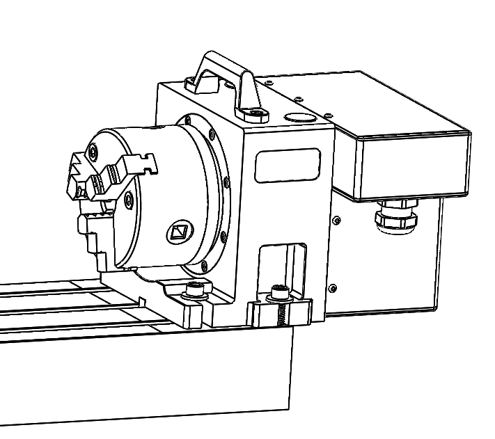
Put the microARC 4 on the machine table. There are several mounting configurations available, depending on the particular needs of a given project:
-
Left Side (Using Accessory Mounting Holes) This configuration provides the maximum available X work space. If used with an ATC, the available tool clearance is 10 cm from TTS flange to tool tip with the 4th axis carrying handle removed.
-
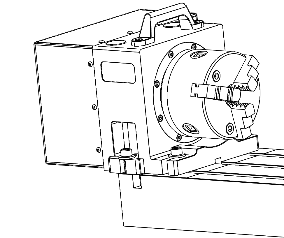
b. Right Side (Using Accessory Mounting Holes) Using the 4th axis on the far right side of the machine table provides the most X work envelope, but interferes with the right side enclosure window, if installed.
c. Right Side (Using 6" Through-Bolts into T-Slots) X work envelope is reduced in this configuration, but it provides clearance for long tooling in the ATC.
-
Feed the motor cable under the electrical cabinet and plug it into the 7-pin connector you installed with the driver kit.
-
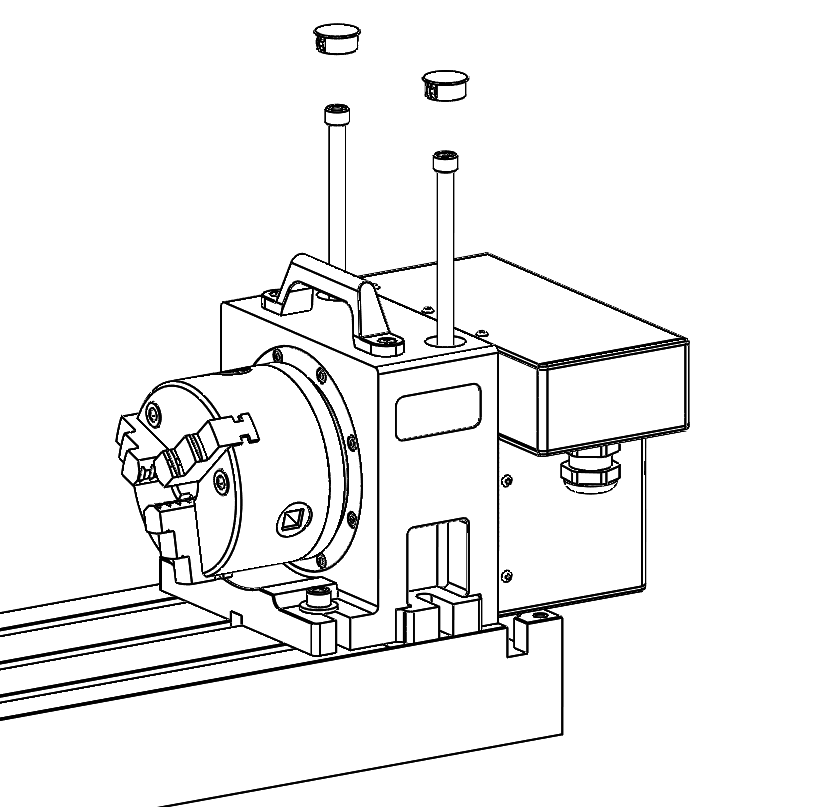
Loosely install the 5/16" mounting bolts, using either the threaded accessory mounting holes on your machine table or T-nuts.
-
Use the key on the bottom of the 4th axis to perform a rough alignment of the unit to the T-slots in your machine's table. If you need to perform a precise alignment, put a straight test bar into the chuck and sweep along it in X with an indicator. Adjust the orientation of the 4th axis until the reading does not deviate during the sweep.
-
Tighten the mounting hardware with a hex wrench.
Center the Chuck Mounting Plate
-
Remove the chuck from the 4th axis, if installed.
-
From the PathPilot interface, verify that you can rotate the 4th axis with either the jog keys on the keyboard or the jog shuttle.
-
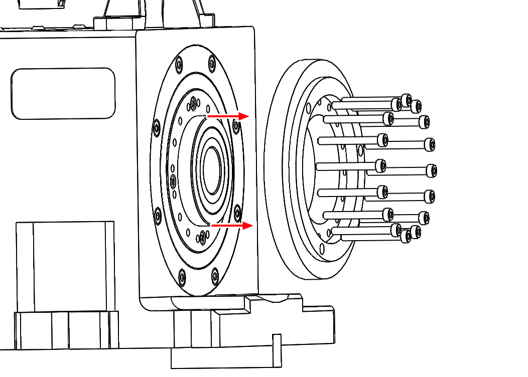
The mounting plate is designed for a loose fit onto the output of the harmonic drive. This allows you to adjust the center of rotation to control runout at the chuck.
-
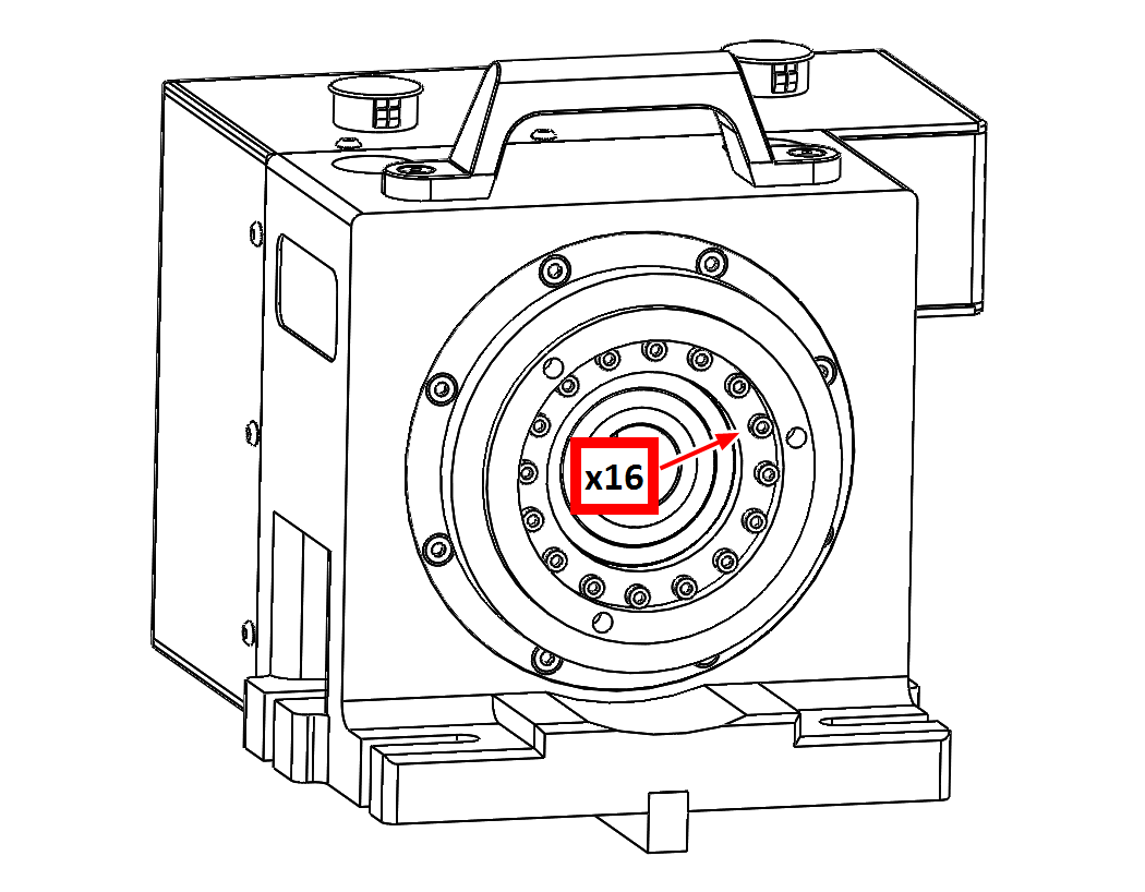
Slightly loosen the 16 M3 button head cap screws that hold the chuck mounting plate to the output of the harmonic drive. They should still be snug enough that the mounting plate is held in place by friction but can be nudged with a dead-blow hammer.
-
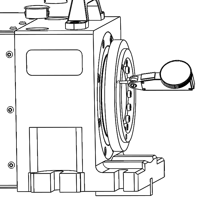
Put a the tip of a dial test indicator on the mounting flange for the chuck.
-
Using PathPilot, jog the 4th axis 360 degrees, noting the spot where the indicator is highest.
-
Using the dead-blow hammer, gently tap the highest indicated spot towards the center and repeat the 360 degree sweep. Continue adjusting the high spot towards the center of rotation and sweeping until you reach your desired runout.
-
Tighten the 16 M3 mounting screws by hand to 1.1 Nm.
-
Reinstall the chuck or ER-40 collet holder.
Maintenance
The microARC 4 is designed to require little to no regular maintenance. The harmonic drive used in the 4th axis is a high-quality sealed unit that you don't need to open and grease. If you do open your unit for any reason, replace any lost grease with Sumiplex MP No. 2. Full grease capacity for the harmonic drive is approximately 16 grams.
After the First Use
Examine the electrical connectors that you installed with "Install the A-Axis Motor Driver" (page 6) Make sure that all screw terminals are still snug and the green terminal connectors are seated firmly.
After Each Use
-
Wipe down the outer diameter of the chuck and clean any chips that may have accumulated below the chuck.
-
Examine the main output seal on the front of the unit behind the chuck adapter. Confirm that no chips are caught in the seal to avoid wear and premature failure.
Once a Month
Remove the 4th axis from the machine table and look for corrosion underneath. If necessary, stone the machine table surface until it's smooth and apply a layer of corrosion-inhibiting spray (like as Boeshield T-9).
To view a PDF version of your manual, go to Tormach document TD10749.
If you have additional questions, we can help. Create a support ticket with Tormach Technical Support at tormach.com/how-to-submit-a-support-ticket for guidance on how to proceed.