Install the Flood Coolant Kit
Adjust the Coolant Pump Motor Strapping
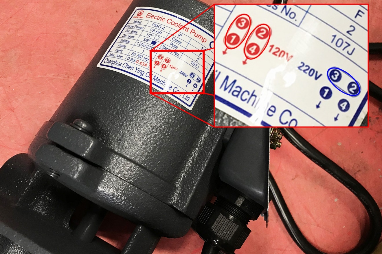
Because the coolant pump is dual voltage, you may need to adjust the motor strapping.
-
Identify the jumper configuration diagram. The coolant pump motor strapping varies by machine:
-
1100 (All Models) 220 Vac (high volt)
-
770 (All Models) 120 Vac (low volt)
-
-
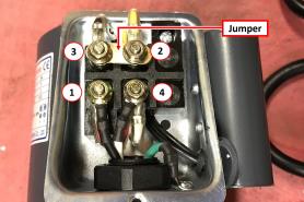
Remove the access cover on the coolant pump.
-
Reference the configuration diagram and move the jumper to the 220 Vac (high volt) position. Don't change the position of any wires – just the jumper that connects the terminals.
-
Reinstall the access cover on the coolant pump.
Set Up the Flood Coolant Kit
-
Attach the threaded elbow into the pump with a 22 mm open-ended wrench. Twist the elbow so that it’s pointing up.
-
Attach the coolant pump to the coolant tank with the four M6 × 1 - 22 screws provided.
-
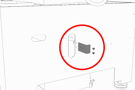
Remove the coolant hose bracket from the rear of the Machine Stand. Set the hardware aside.
-
Attach the provided Y-fitting to the coolant hose bracket, and then install the coolant hose bracket back on the Machine Stand using the hardware that you set aside in Step 4.
-
Identify the two provided coolant hoses: the self-retracting coolant hose and the long coolant hose.
-
Put the self-retracting coolant hose into the top of the Y-fitting.
-
Put the provided plug into the remaining side of the Y-fitting.
-
Cut a 3 in. (76 mm) piece of the longer coolant hose with snips.
-
Put the newly cut piece of the coolant hose into the bottom of the Y-fitting. Then, put the provided elbow onto the its loose end.
-
Put the remainder of the long coolant hose into the open end of the elbow.
-
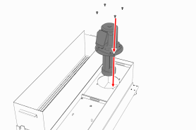
Route the loose end of the long coolant hose through the Machine Stand, through the energy chain, and to the spindle head.
-
Attach the coolant manifold to the spindle nose with the two screws provided.
-
Put the loose end of the long coolant hose into the coolant manifold.
-
Route the loose end of the self-retracting coolant hose through the rear of the Machine Stand, and then put it into the elbow on the coolant pump.
-
Move the coolant tank into the Machine Stand.
-
Route the power cord on the coolant pump to the rear of the electrical cabinet, and connect it to the Coolant Pump Power outlet.
-
Verify that the coolant setup operates properly:
-
From the PathPilot interface, on the Main tab, select Coolant.
The coolant pump powers on. -
Select Coolant again.
The coolant pump powers off.
-
-
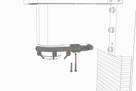
Secure coolant tank’s front panel to the Machine Stand with the two provided M8 × 1.25 – 16 flanged button head cap screws. Adjust the front panel alignment as necessary using the six mounting screws securing the front panel to the coolant tank.
Looking for more information?
This is a section of the 1100M operator's manual. To view the whole manual, go to Tormach document UM10540.
If you have additional questions, we can help. Create a support ticket with Tormach Technical Support at tormach.com/how-to-submit-a-support-ticket for guidance on how to proceed.