Background
Your machine axes require power and control signals to work. If either of those are disrupted you can lose any or all of your axes motion. If only one motor is not working go to, One Axis Won't Move (or Only Moves in One Direction), and Other Axes Move - 1100M.
Tools
-
Digital multimeter
-
Metric Allen Keys
-
Small Flat Blade Screw Driver
Reseat the Connectors on the Machine Control Board and Motors
Reason: Control signals aren't reaching the electronic driver modules/servo motors.
-
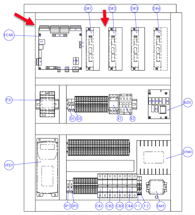
Inspect the stepper driver controller lights.
-
Some controller lights are on: One Axis Won't Move (or Only Moves in One Direction), and Other Axes Move - 1100M .
-
All the controller lights are off: Continue to the next step.
-
-
Power off the machine.
-
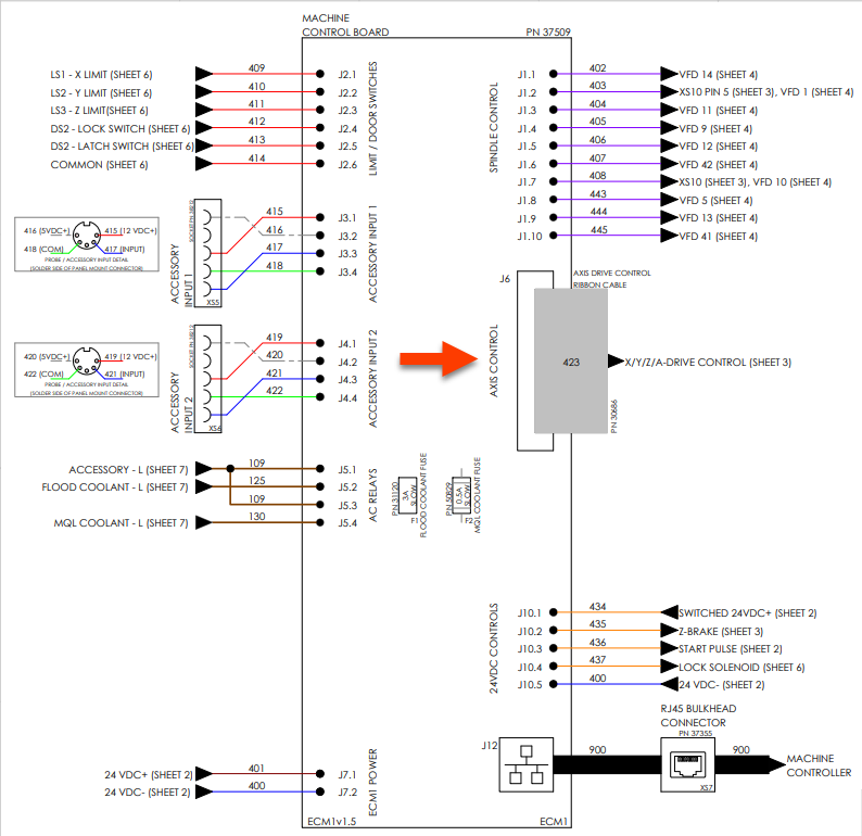
Examine the data cable at the machine control board and the axes drivers.
-
Machine control board: J6 (26 pin IDC ribbon cable)
-
Stepper driver controllers: 10 pin IDC (ribbon cable)
-
423.1 (X-axis)
-
423.2 (Y-axis)
-
423.3 (Z-axis)
-
-
-
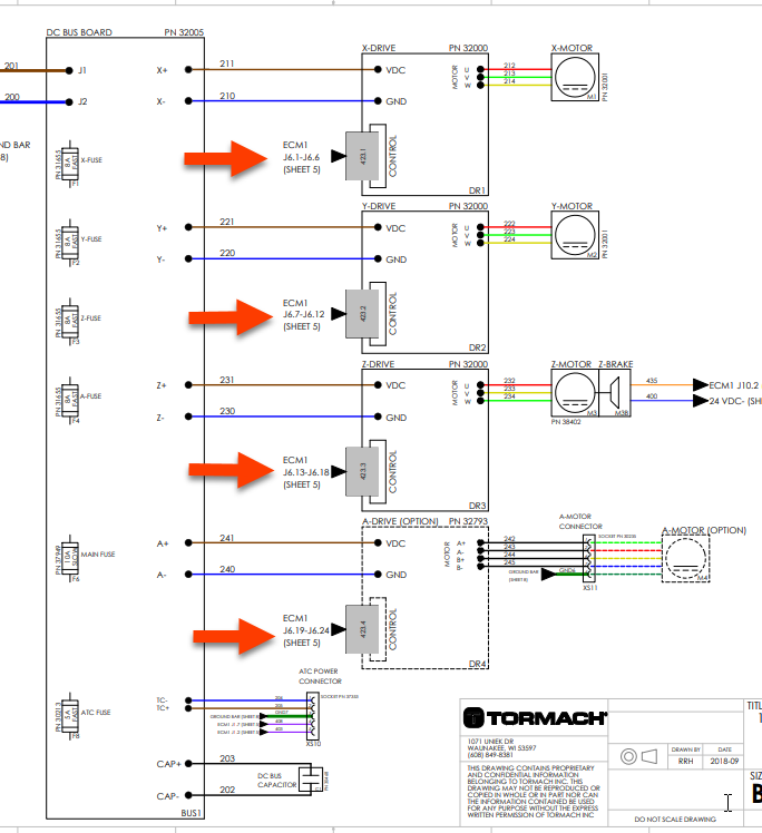
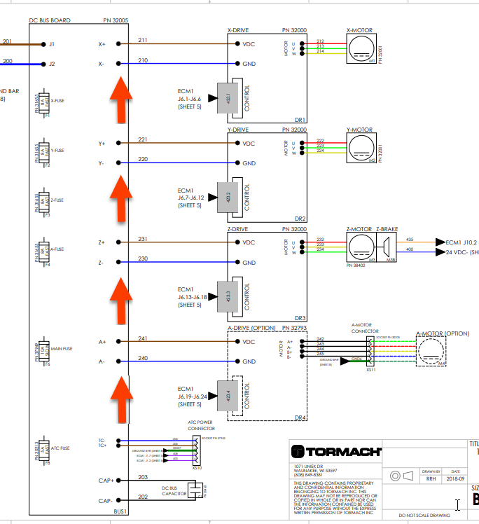
Examine the power and control cables at the DC-BUS and the stepper driver controllers removing, inspecting, and re-connecting them to ensure they are seated.
-
DC-Bus/Stepper driver controllers: Spade connectors/Degson style
-
210/211 (X-axis)
-
220/221 (Y-axis)
-
230/231 (Z-axis)
-
-
-
If there is any discoloration, replace the cable and driver.
-
Continue to the next troubleshooting topic.
Inspect the DC-BUS board
Reason: The DC-BUS or DC power supply is malfunctioning.
-
Inspect the DC-BUS for power by determining if the green power light is illuminated.
-
If it does: The stepper driver controllers will be illuminated, if the DC Bus Axis Fuses are not blown. To learn how to check individual fuses, see: One Axis Won't Move (or Only Moves in One Direction), and Other Axes Move - 1100M | Inspect the DC BUS board
-
If it doesn’t: Continue to the next step.
-
-
Power off the machine.
-
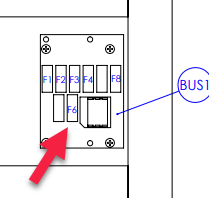
Measure the resistance across the F6 fuse with digital multimeter set to resistance.
-
Replace the fuse if the digital multimeter reads OL, shows a resistance in the MΩ, and/or doesn’t produce continuity tone.
-
If the fuse measures 0-5 Ω, reinstall it into the DC-BUS.
-
-
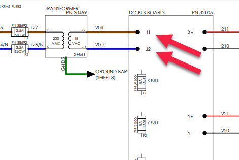
Power on the machine and measure the Vac entering the DC-BUS on:
-
200 (J2)
-
201 (J1)
-
-
Continue to the next troubleshooting topic.
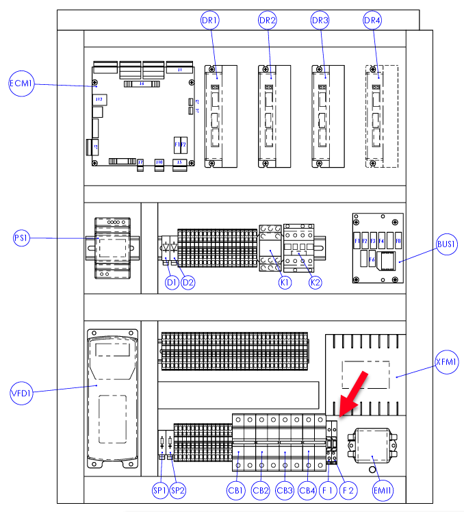
Inspect the XMF1 Transformer
Reason: The fuse(s) have blown.
-
Power off the machine.
-
Remove and measure the resistance across the F1 then F2 fuses with digital multimeter set to resistance.
-
Replace the fuses if the digital multimeter reads OL, shows a resistance in the MΩ, and/or doesn’t produce continuity tone.
-
If the fuses measures 0-5 Ω reinstall them.
-
-
Continue to the next troubleshooting topic.
Inspect the Controller and Machine Communication
Reason: PathPilot isn’t commanding the move, there is a cable problem, or a controller problem.
-
Power on the machine and take it out of reset.
-
Verify that the selected machine configuration in the bottom right corner of PathPilot is correct.
-
Select the Main tab, then, on the keyboard, press the Esc key.
-
Jog the axes and, from the PathPilot interface, examine the value displayed in their DRO fields.
-
If the position doesn't change: There's a problem with the controller.
-
If the position changes: There is a communication or hardware issue.
-
-
Continue to the next troubleshooting topic.
Check the K1 Contactor
Reason: The K1 is defective.
-
Power on the machine and take it out of reset.
-
Inspect the K1 for an illuminated red LED that indicates it has power.
-
If the light is on: The K1 is latched. Using a digital multimeter set to Vac, measure for 220 Vac between:
-
114N
-
115
-
-
If the light is not on: Continue to the next step.
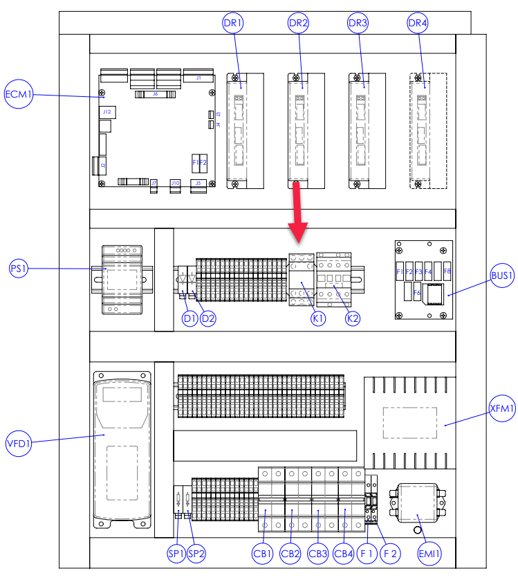
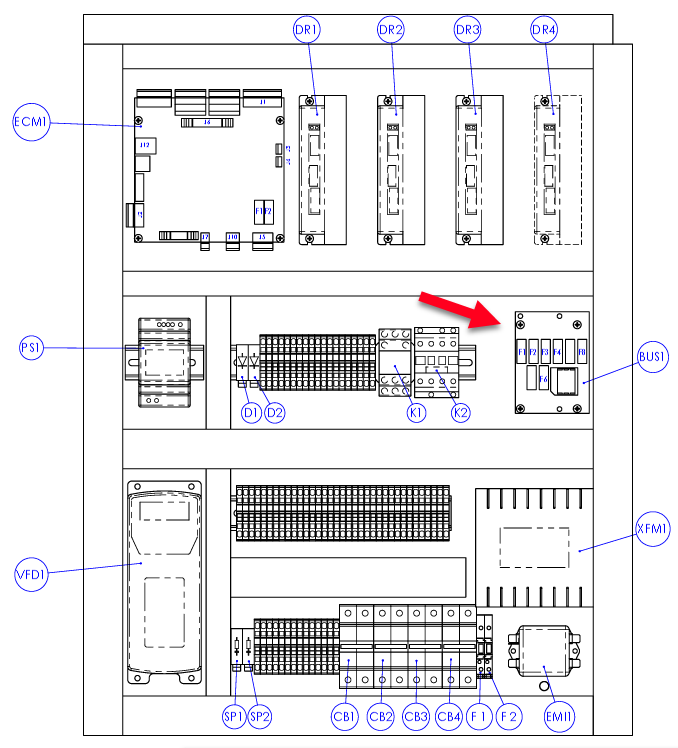
M Electrical Cabinet K1 Location
-
-
Press and hold the Reset button on the operator box and observe the K1 LED. Then release the Reset button and observe the K1 LED.
-
If the light only stays on when the button is pressed: There is a loose coil wire, short, or the K1 has malfunctioned.
-
If the light never comes on: See Machine Won't Power On - 1100M
-